Semiconductor device and preparation method thereof

A semiconductor and device technology, applied in the field of semiconductor devices and their preparation, can solve the problems of dielectric residue, photolithographic alignment and alignment cannot be measured, poor step filling, etc., to achieve good step coverage and solve OVL measurement problem effect

Active Publication Date: 2015-07-01
SEMICON MFG INT (SHANGHAI) CORP
View PDF14 Cites 7 Cited by
  • Summary
  • Abstract
  • Description
  • Claims
  • Application Information

AI Technical Summary

Problems solved by technology

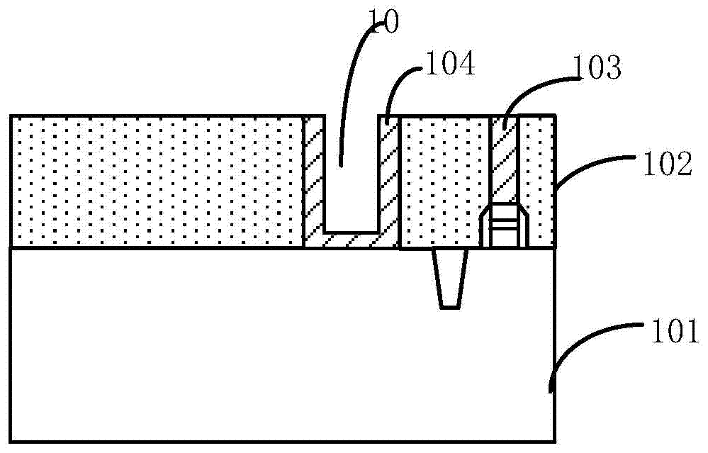
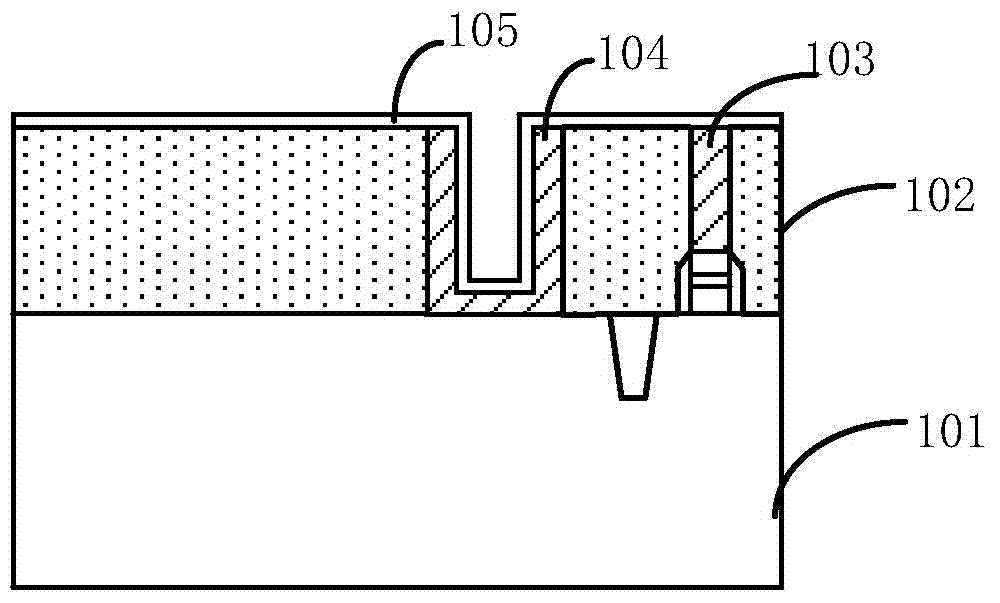
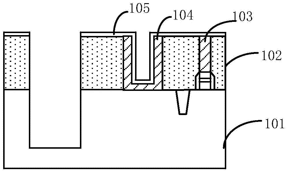
Perform the TSV process after forming the contact hole, refer to Figure 1b , forming a protective layer 105 on the interlayer dielectric layer 102, on the pattern of the contact hole 103, and in the photomark pattern (photo mark) 104. At present, in the semiconductor process, SiN is usually deposited by CVD as the protective layer, The method and cost are relatively mature and simple. In the Cu-Cu bonding process (TSV VIA middle) in wafer bonding, it is usually used as the protective layer of CT and the stop layer of TSVCMP. However, due to the poor step filling of SiN (step coverage) capability, the photo mark area cannot be well filled, and there are still large gaps; pattern the interlayer dielectric layer 102 to form through-silicon via grooves, such as Figure 1c As shown, wherein the protection layer 105 forms a good protection for the CT region; then deposits a through-silicon via isolation layer 106 (TSV isolation), and the through-silicon via isolation layer 106 has a good step coverage (step coverage) capability , therefore, the void in the photolithography mark hole region (CT photo mark) is completely filled, as Figure 1d As shown, conductive material is then filled in the TSV groove and planarized to the protective layer 105 to form a TSV structure, such as Figures 1e-1f As shown; the protective layer 105 is finally removed, but after removal, the TSV release layer 106 (oxide) remains in the lithography mark hole area (CT photo mark) and cannot be removed, so that the subsequent first metal layer lithography ( M1photo) process alignment CT becomes difficult, and it is not conducive to the measurement of alignment (OVL)
[0007] In the prior art, SIN is usually deposited by CVD as a protective layer, and the method and cost are relatively mature and simple. In the TSV VIA middle process, it is also usually used as a protective layer for CT and a stop layer for TSV planarization. The CT pattern of the photo mark (photo mark) and the aperture of the contact hole as an interconnection have a huge CD difference, resulting in more dielectric residues in the CT pattern of the photo mark (photo mark) during the TSV process. It is an inevitable problem in the TSV VIA Middle process that SIN is used as a protective layer, and there is no good solution for the time being
[0008] In addition, using SIN as the protective layer of CT in the TSV process will bring some process problems, so that the subsequent M1 photolithography process photolithography (photo) cannot be aligned and aligned (OVL) and cannot be measured. How to solve this problem is The biggest challenge facing the current TSV process

Method used


Image

  • Semiconductor device and preparation method thereof
  • Semiconductor device and preparation method thereof
  • Semiconductor device and preparation method thereof

Examples


Embodiment Construction

[0046] In the following description, numerous specific details are given in order to provide a more thorough understanding of the present invention. It will be apparent, however, to one skilled in the art that the present invention may be practiced without one or more of these details. In other examples, some technical features known in the art are not described in order to avoid confusion with the present invention.

[0047] For a thorough understanding of the present invention, a detailed description will be presented in the following description to explain the method of manufacturing the semiconductor device of the present invention. Obviously, the practice of the invention is not limited to specific details familiar to those skilled in the semiconductor arts. Preferred embodiments of the present invention are described in detail below, however, the present invention may have other embodiments besides these detailed descriptions.

[0048] It should be noted that the terms...


PUM

PropertyMeasurementUnit
thicknessaaaaaaaaaa

Abstract

The invention relates to a semiconductor device and a preparation method thereof. The method comprises the steps of providing a semiconductor substrate, and forming an interlayer dielectric layer on the semiconductor substrate, wherein the interlayer dielectric layer is internally provided with a contact hole and a photoetching mark hole, and the photoetching mark hole is provided with a gap; depositing a sacrificial material layer so as to completely fill the gap; forming a protection layer on the interlayer dielectric layer and the sacrificial material layer; forming a silicon through hole in the semiconductor substrate and the interlayer dielectric layer; removing the protection layer so as to expose the sacrificial material layer; and removing the sacrificial material layer so as to expose the gap. According to the invention, a-C is used to act as the protection layer of CT in the silicon through hole preparation (TSV VIA middle) process, and compared with SIN, the a-C has a better step coverage ability and can be completely removed, thereby not affecting follow-up photoetching (M1photo) alignment for a first metal layer, and effectively solving a problem of OVL measurement.

Description

technical field [0001] The invention relates to the field of semiconductors, in particular, the invention relates to a semiconductor device and a preparation method thereof. Background technique [0002] In the field of electronic consumption, multi-function devices are more and more popular among consumers. Compared with devices with simple functions, the production process of multi-function devices will be more complicated, such as the need to integrate multiple chips with different functions on the circuit board, so 3D integrated circuit (integrated circuit, IC) technology, 3D integrated circuit (integrated circuit, IC) is defined as a system-level integrated structure, stacking multiple chips in the vertical plane direction, thereby saving space, the edge of each chip Multiple pins can be drawn out as needed, and these pins can be used to interconnect the chips that need to be connected to each other through metal wires, but the above method still has many shortcomings, ...

Claims


Application Information

Patent Timeline
Patent Type & Authority Applications(China)
IPC IPC(8): H01L21/768H01L23/48H01L23/544
CPCH01L21/76805H01L23/48H01L23/544
Inventor 戚德奎李新
Owner SEMICON MFG INT (SHANGHAI) CORP
Why Eureka
Try Eureka