
Radiating device of electronic element

A heat dissipation device and electronic component technology, which is applied in the direction of cooling/ventilation/heating transformation, etc., can solve the problems of high junction temperature of heating elements, aging service life of phosphor powder, and drift of main wavelength of light emission, etc. Stable performance and high cooling efficiency

Inactive Publication Date: 2015-07-01
JIANGSU UNIV
View PDF4 Cites 2 Cited by
  • Summary
  • Abstract
  • Description
  • Claims
  • Application Information

AI Technical Summary

Problems solved by technology

At present, the drive current of power LEDs is as high as 1A, which will cause heat accumulation inside the chip, resulting in a series of problems such as drift of the main wavelength of light emission, decrease in light extraction efficiency, accelerated aging of phosphor powder, and shortened service life. Natural convection in the existing technology Heat dissipation cannot effectively solve the problem of high junction temperature of heating elements

Method used


Image

  • Radiating device of electronic element
  • Radiating device of electronic element
  • Radiating device of electronic element

Examples


Embodiment Construction

[0024] The present invention will be further described below in conjunction with the accompanying drawings and specific embodiments, but the protection scope of the present invention is not limited thereto.

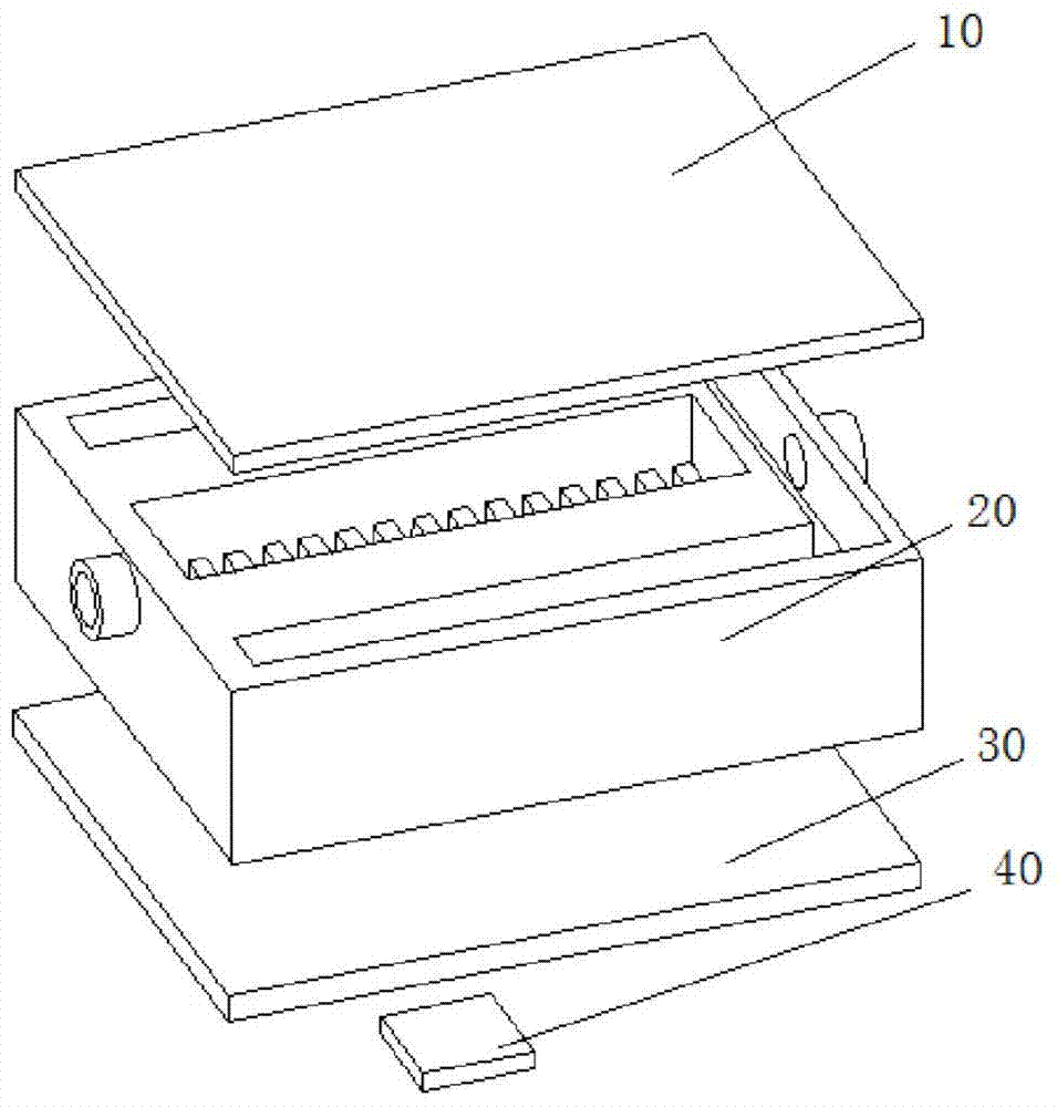
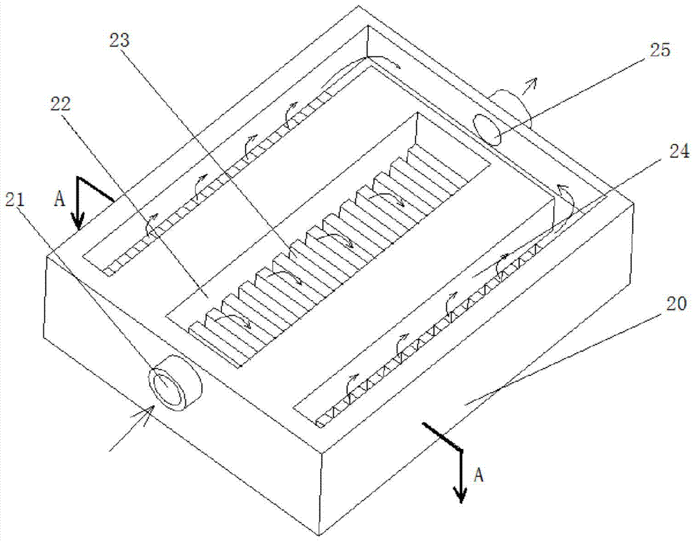
[0025] Such as figure 1 The heat dissipation device for the electronic components shown is composed of an upper substrate 10, a microgroove group heat sink 20, and a lower substrate 30. The shape of the microgroove group heat sink is a box with an upper opening, and the upper substrate 10 is located above the microgroove group heat sink. , is fixedly connected with the heat sink 20 of the micro-groove group to form a sealing structure, which can seal and protect the heat sink 20 of the micro-groove group; the lower substrate 30 and the lower surface of the heat sink 20 of the micro-groove group are bonded by thermal silica The material of the lower substrate 30 is silicon or heat-conducting metal, which is a transition body for heat transmission. The heat-conducting silic...


PUM


Abstract

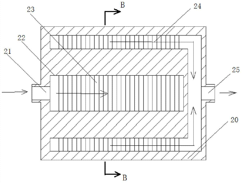
The invention provides a radiating device of an electronic element. The radiating device of the electronic element adopts a sealed type active circular heating; a sealing structure is formed through an upper substrate and a microgroove group heat sink; the inner structure of the microgroove group heat sink is that a middle flow way is encircled by two side flow ways, and two side flow ways are interconnected to the bottom part of the middle flow way, and microgroove groups are respectively arranged on the two side flow ways and the middle flow way; upper and lower faces of a lower substrate are respectively bonded with the bottom face of the microgroove group and an electronic element; a cross groove path of the microgroove group heat sink makes the pressure and flowing distributions of cooling mediums more uniform; the downwards impact jet flow makes the heat exchanging efficiency higher.

Description

technical field [0001] The invention belongs to the field of heat dissipation devices, in particular to a heat dissipation device for electronic components. Background technique [0002] Light Emitting Diode (LED) is a new competitive solid light source in the 21st century. Compared with traditional light sources, it has the advantages of long service life, small size, low energy consumption, high reliability, fast response, flexible design, and flexible control. Under the background of "energy saving, environmental protection, and low-carbon economy", LED, as the "fourth generation" lighting source, conforms to the trend of the times and is being widely used in many fields. However, a key factor that restricts the continued promotion of LED light sources is the junction temperature of LED chips. At present, the drive current of power LEDs is as high as 1A, which will cause heat accumulation inside the chip, resulting in a series of problems such as drift of the main wavel...

Claims


Application Information

Patent Timeline
IPC IPC(8): H05K7/20
Inventor 王静李小华包伟伟赵新杰蔡忆昔张纯李慧霞
Owner JIANGSU UNIV
Learn More