A thrombus suction catheter and its application

A technique for suctioning a catheter and a thrombus, which is applied to a thrombus suction catheter and its application field, can solve the problems of high preparation cost, cumbersome use method, complicated structure of a thrombus removal device, etc., and achieves a simple overall structure and efficient and convenient operation for thrombus extraction. Effect

Inactive Publication Date: 2016-03-16
黄经春
View PDF9 Cites 0 Cited by
  • Summary
  • Abstract
  • Description
  • Claims
  • Application Information

AI Technical Summary

Problems solved by technology

[0007] However, the structures of the above-mentioned three types of thrombus removal devices are relatively complicated, and the preparation cost is high and the use method is loaded down with trivial details.

Method used


Image

  • A thrombus suction catheter and its application
  • A thrombus suction catheter and its application
  • A thrombus suction catheter and its application

Examples


Embodiment 1

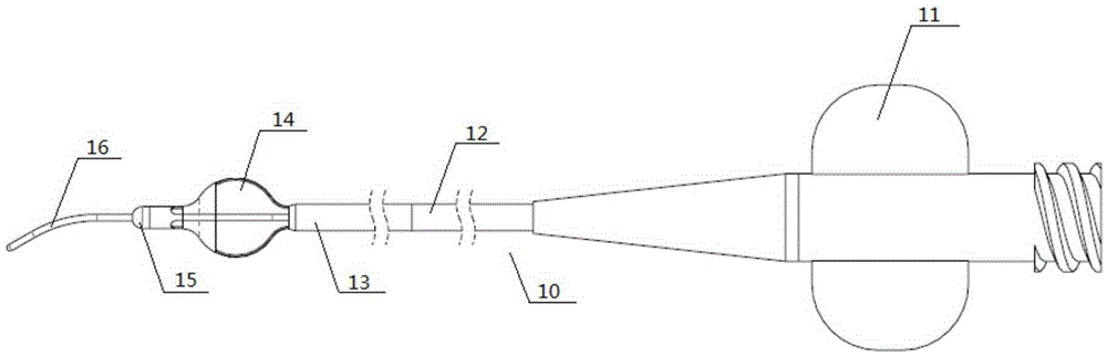
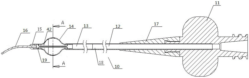
[0040] A thrombus suction catheter, comprising a suction catheter body 12, a guide wire 16 provided at the front of the suction catheter body 12 through a guide wire seat 15, and a guide wire 16 disposed through the rear of the suction catheter body 12. Luer connector 11 ; a thrombus stripping frame 14 is arranged between the suction catheter body 12 and the guide wire holder 15 .

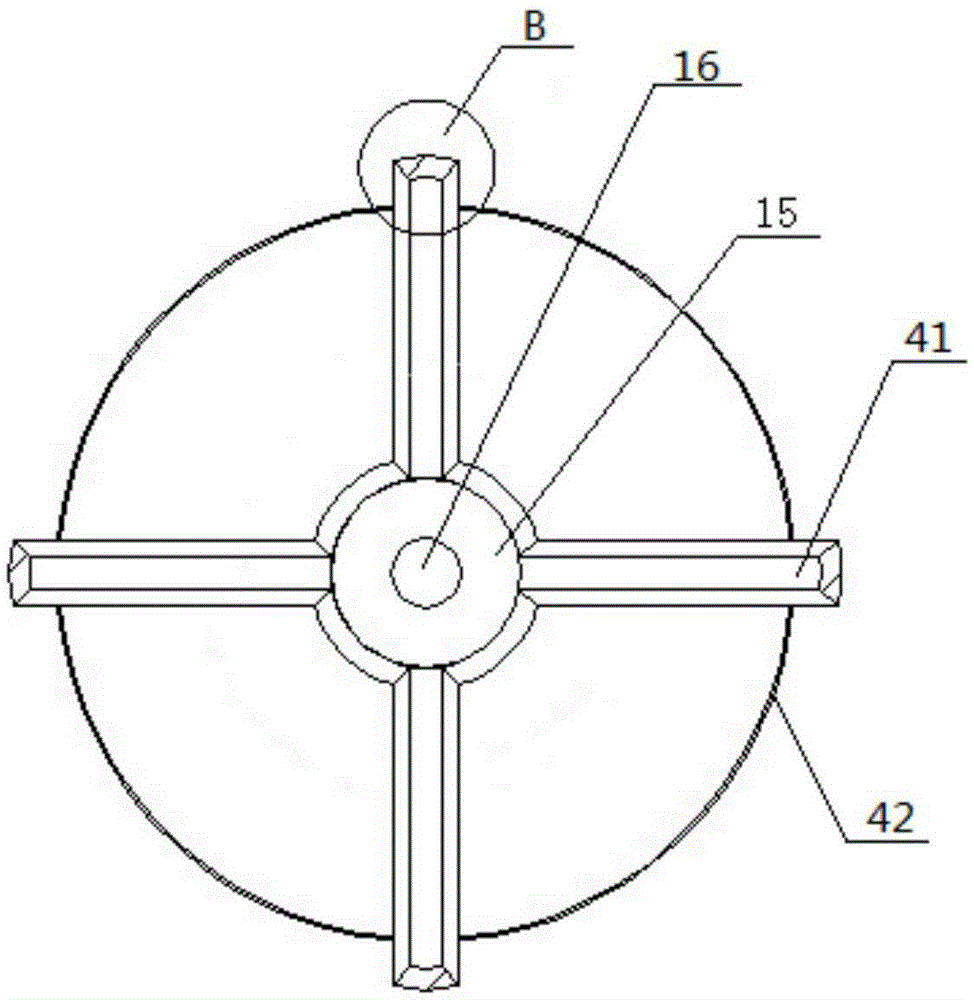
[0041] The thrombus dissection rack 14 is a cutting blade 41 whose middle section is bulged along the radial direction of the suction catheter body 12 .

[0042] At least one edge of the cutting blade is an acute edge.

[0043] like Figure 4 As shown, the outer edge of the section C of the cutting blade includes two angles α and β. The α and β may be one of the acute angles, and the α and β may also be both acute angles, so as to ensure that the The outside corners are sharp enough. When the thrombus dissection rack is operated to rotate in the blood vessel, the thrombus dissection rack can com...

Embodiment 2

[0045] like figure 1 shown.

[0046]The thrombus suction catheter as described in Embodiment 1 is different in that the thrombus stripping rack 14 includes more than two arc-shaped cutting sheets, and one end of the arc-shaped cutting sheets, that is, one end of the thrombus stripping rack 14, passes through the The guide wire holder 15 is connected to the guide wire 16 ; the other end of the arc-shaped cutting blade, that is, the other end of the thrombus dissection rack 14 , is connected to the suction catheter body 12 .

[0047] The arc-shaped cutting blade includes an outer surface and an inner surface, and the width of the inner surface is smaller than the width of the outer surface.

[0048] The radius of curvature of the outer arc of the thrombus stripping rack is less than or equal to 2 mm.

[0049] An intercepting membrane is arranged between the guide wire holder and the thrombus stripping rack, and the intercepting membrane is a permeable membrane.

Embodiment 3

[0051] like figure 2 , 3 , 4, and 5.

[0052] A thrombus suction catheter as described in Embodiment 2, the difference is that between the guide wire holder 15 and the thrombus stripping rack 14, a drain hole 19 and an intercepting membrane 42 are arranged in sequence, and the intercepting The membrane is a non-permeable membrane.


PUM


Abstract

A thrombus aspiration catheter comprises an aspiration catheter body, a guide wire and a Luer taper, wherein the guide wire is arranged at the front portion of the aspiration catheter body through a guide wire base, and the Luer taper is arranged at the rear portion of the aspiration catheter body in a through mode. The thrombus aspiration catheter is characterized in that a thrombus stripping frame is arranged between the aspiration catheter body and the guide wire base; the thrombus stripping frame comprises cutting slices, and the middle section of each cutting slice protrudes in the radial direction of the aspiration catheter body; at least one edge of each cutting slice is an acute-angle edge. The outer edge of the section C of each cutting slice involves the angle alpha and the angle beta, one of the angle alpha and the angle beta can be an acute angle, alternatively, both the angle alpha and the angle beta can be acute angles, and it is guaranteed that the outer corner of the section C is sharp enough. When operated to rotate in a blood vessel, the thrombus stripping frame can thoroughly clear away thrombi.

Description

technical field [0001] The invention relates to a thrombus suction catheter and its application, belonging to the technical field of medical devices. Background technique [0002] Acute myocardial infarction (AMI) is a common cardiovascular and cerebrovascular emergency in clinical practice. Currently, the most effective treatment is emergency percutaneous coronary intervention (PCI) of the infarct-related arteries for effective revascularization. During emergency PCI, there are still some patients with "slow blood flow" or "no reflow" phenomenon. One of the main reasons is that fresh thrombus and / or plaque fall off during routine balloon dilation and stent implantation. The resulting distal microvascular embolism seriously affects the immediate treatment effect and long-term prognosis of patients with acute ST-segment elevation myocardial infarction (STEMI). Therefore, the application of auxiliary devices that may reduce thromboembolism in emergency PCI, removal of intrac...

Claims


Application Information

Patent Timeline
Patent Type & Authority Patents(China)
IPC IPC(8): A61B17/22
CPCA61B17/00234A61B17/22A61B2017/00243A61B2017/22038A61B2017/22079
Inventor 黄经春郝树彬郭世文
Owner 黄经春
Why Eureka
Try Eureka