Micro-strip difference rectification antenna based on WIFI frequency band

A rectenna and microstrip line technology, applied in the direction of antenna, slot antenna, radiating element structure, etc., can solve problems such as affecting the receiving performance of the device, reduce the actual processing difficulty, reduce the impedance variation range, and improve the system performance. Effect

Inactive Publication Date: 2015-07-08
SYSU CMU SHUNDE INT JOINT RES INST +1
View PDF2 Cites 24 Cited by
  • Summary
  • Abstract
  • Description
  • Claims
  • Application Information

AI Technical Summary

Problems solved by technology

However, due to the complex microstrip line structure of the rectenna, it is easy to generate parasitic capaci

Method used


Image

  • Micro-strip difference rectification antenna based on WIFI frequency band
  • Micro-strip difference rectification antenna based on WIFI frequency band
  • Micro-strip difference rectification antenna based on WIFI frequency band

Examples


Embodiment 1

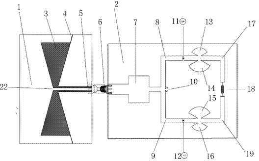
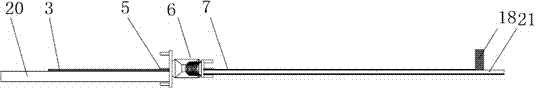
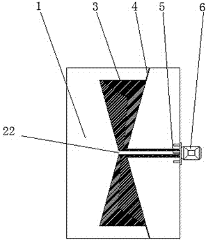
[0028] See attached Figure 1-4 , the present embodiment is based on a high output voltage microstrip differential structure rectifying antenna in the Wifi frequency band, including a slit improved CPW butterfly omnidirectional antenna 1 and a microstrip differential structure rectifying circuit 2, and the CPW butterfly omnidirectional antenna 1 is made in On the upper metal surface 20 of the double-sided copper clad FR4 epoxy resin dielectric substrate with an area of ​​30mm*45mm, the lower layer is a bare dielectric layer without copper cladding. Its composition includes: a trapezoidal exposed medium area 3 , a continuous slotted area 4 , a central feeder 5 , a T-shaped power divider 22 , and an SMA male-female joint 6 . The dielectric constant of the substrate medium is 4.4, the thickness is 1.6mm, the thickness of the metal layer copper foil is 0.035mm, and the loss tangent angle is 0.02. The impedance of the antenna system is 50 ohms, and it works in the WIFI frequency b...


PUM

PropertyMeasurementUnit
Radianaaaaaaaaaa

Abstract

The invention provides a high output voltage micro-strip difference rectification antenna based on a WIFI frequency band. The micro-strip difference rectification antenna based on the WIFI frequency band comprises a micro-strip receiving antenna and a micro-strip difference rectification circuit, wherein the micro-strip receiving antenna and the micro-strip difference rectification circuit are manufactured on a metal layer on the upper layer of a two-sided copper-coated dielectric substrate and connected through an SMA hermaphrodite connector. The micro-strip difference rectification antenna based on the WIFI frequency band adopts a disc-shaped slotting technology, so that the antenna has high direction gains, a wide work frequency band and low loss. A micro-strip line feed method is adopted, a multi-unit array can be formed easily, and the micro-strip difference rectification antenna based on the WIFI frequency band can be applied to large-power occasions. The positive and negative electrodes of a rectification diode are arranged on one side of a dielectric slab and are connected in the rectification circuit in series, and platemaking is easy; the rectification circuit is of a symmetrical structure, the size of the circuit is reduced, the complexity and machining difficulty of the system are reduced, and the integration degree is improved; the rectification circuit adopts a differential voltage output mode, the whole design is not provided with via holes, the parasitic parameter is small, the system performance is good, and output voltage is high.

Description

technical field [0001] The invention relates to the field of wireless energy transmission, and more particularly to a microstrip differential rectifying antenna based on a WIFI frequency band. Background technique [0002] Wireless Power Transmission (WPT: Wireless Power Transmission) technology breaks the traditional mode of energy transmission through cables. It uses microwave radiation, electromagnetic induction and other methods to transmit energy wirelessly. Among them, microwave power transmission (MPT: Microwave Power Transmission) has attracted the attention of the scientific community 200 years ago due to its long transmission distance, high distance efficiency ratio, flexible direction, and easy integration. At the end of the 19th century, American scientist Nikola Tesla first proposed the concept of MPT. Modern MPT technology began in the United States and Japan in the 1960s, and was first used in high-power applications, including microwave-driven unmanned aeria...

Claims


Application Information

Patent Timeline
IPC IPC(8): H01Q1/38H01Q13/08H01Q13/10
Inventor 谭洪舟张全琪梁晓东邓华超
Owner SYSU CMU SHUNDE INT JOINT RES INST
Why Eureka
Try Eureka