High-temperature reverse blowing process and device thereof
A backflushing device and high-temperature technology, which is applied in the separation of dispersed particles, chemical instruments and methods, and filtration of dispersed particles, can solve the problems of easy damage to the pulse valve and unsatisfactory cleaning effect, and achieve the effect of avoiding unstable work
- Summary
- Abstract
- Description
- Claims
- Application Information
AI Technical Summary
Problems solved by technology
Method used
Image
Examples
Embodiment 1
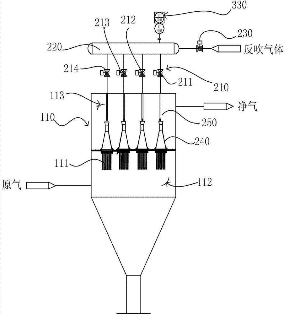
[0025] Such as figure 1 As shown, the blowback device of this embodiment includes an air bag 220, the air bag 220 is provided with an air inlet and four air outlets, and the air inlet is connected to a superheated steam source through an air inlet pipe. The air inlet pipe is provided with an air inlet valve 230, and each air outlet is connected with an air outlet pipe, and the air outlet pipe is connected with a blowing pipe 240, and the air outlet pipe is provided with an air outlet valve group 210, and the air outlet valve group 210 includes sequentially arranged on The first high-temperature valve 211, the second high-temperature valve 212, the third high-temperature valve 213 and the fourth high-temperature valve 214 on the gas outlet pipe, the gas outlet valve group 210 and the inlet valve 230 are all high-temperature ball valves, and the air bag 220 A pressure gauge 310 is provided. In this embodiment, the blowback device is used in the gas blowback device. The gas filt...
Embodiment 2
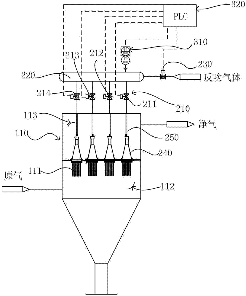
[0033] Such as figure 2 As shown, the blowback device of this embodiment includes an air bag 220, and the air bag 220 is provided with an air inlet and four air outlets, and the air inlet is connected with a compressed nitrogen source through an air inlet pipe, and An air inlet valve 230 is provided, and each air outlet is connected with an air outlet pipe, and the air outlet pipe is connected with a blowing pipe 250, and the air outlet pipe is provided with an air outlet valve group 210, and the air outlet valve group 210 includes sequentially arranged on the air outlet pipe. The first high-temperature valve 211, the second high-temperature valve 212, the third high-temperature valve 213 and the fourth high-temperature valve 214, the outlet valve group 210 and the inlet valve 230 are all high-temperature ball valves, and the air bag 220 is provided with a pressure The sensor 310, the pressure sensor 310, the outlet valve group 210 and the inlet valve 230 are all controlled by ...
Embodiment 3
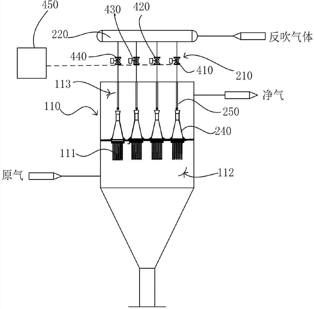
[0041] The difference between this embodiment and Embodiment 1 is that the specified temperature in this embodiment is 400°C, the set pressure threshold is 3Mpa, the outlet valve group and the inlet valve are high-temperature butterfly valves, and the outlet valve group There are three high temperature butterfly valves. Through the above-mentioned high temperature back blowing process and its back blowing device, the back blowing operation can be carried out smoothly while maintaining the required back blowing pressure, so that the filter cake on the surface of the filter element group in the gas filter device is better removed, and the gas filter device The filtration efficiency has been improved.
PUM
 Abstract
Description
Claims
Application Information
 - R&D
- Intellectual Property
- Life Sciences
- Materials
- Tech Scout
- Unparalleled Data Quality
- Higher Quality Content
- 60% Fewer Hallucinations
Browse by: Latest US Patents, China's latest patents, Technical Efficacy Thesaurus, Application Domain, Technology Topic, Popular Technical Reports.
© 2025 PatSnap. All rights reserved.Legal|Privacy policy|Modern Slavery Act Transparency Statement|Sitemap|About US| Contact US: help@patsnap.com


