

Floating type offshore wind plant wave energy auxiliary power generation device
A technology for auxiliary power generation and wind farms, used in wind power generation, wind turbines, wind turbine combinations, etc., can solve the problems of difficulty in production and transportation, large space occupation, large contact area, etc., to solve the problem of unstable power output and power The effect of compensating for lag and ensuring economic benefits
- Summary
- Abstract
- Description
- Claims
- Application Information
AI Technical Summary
Problems solved by technology
Method used
Image

Examples
Embodiment Construction
[0031] Best practice:
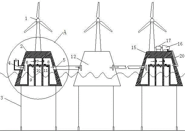
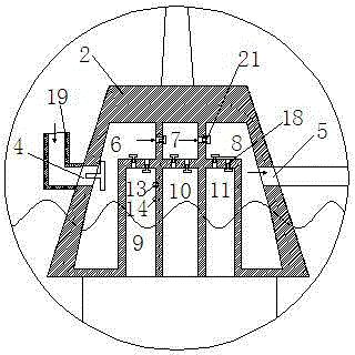
[0032] Refer to attached figure 1 And attached figure 2 The floating offshore wind farm wave energy auxiliary power generation device includes a wind turbine 1 and a floating platform 2. The wind turbine 1 is located on a barge or round platform floating platform 2, and uses sea wind to generate electricity. The floating platform 2 adopts the small volume of the upper part and the large volume of the lower part to ensure sufficient buoyancy, so that the wind turbine floats on the sea surface and controls the water entry depth of the floating platform. The bottom of the floating platform 2 is anchored to the seabed by the rope 3 and kept in a tensioned state to ensure that the floating platform does not vibrate in the vertical direction under the action of sea waves. The internal structures of the floating platforms 2, 12 and 15 are all the same, and the floating platform 2 is taken as an example below for description.
[0033] An air hole is respect...
PUM
 Abstract
Description
Claims
Application Information