
Projection exposure apparatus

An exposure device and projection technology, applied in the field of lithography machines, can solve the problems of rising production and manufacturing costs, high engineering implementation risks, complex manufacturing processes, etc., and achieve low motion quality, improved exposure imaging quality, and guaranteed scanning overlay accuracy. Effect

Active Publication Date: 2015-07-22
SHANGHAI MICRO ELECTRONICS EQUIP (GRP) CO LTD
View PDF6 Cites 10 Cited by
  • Summary
  • Abstract
  • Description
  • Claims
  • Application Information

AI Technical Summary

Problems solved by technology

Therefore, when the objective lens described in this method is used for display panel manufacturing, there will be great difficulties in production efficiency. If it is used for the production of mobile terminal displays with a size of 7 inches or more and 12 inches or less, there will also be manufacturing problems caused by splicing exposure. Problems such as complex process and rising manufacturing costs
[0006] In order to improve the production efficiency of exposure equipment, the United States designed a dual-lens exposure device, which uses two lenses to expose at the same time to reduce the number of step exposures. Although this method can improve production efficiency, it also has the following shortcomings: using 2 One reticle, two sets of mask tables, two sets of illumination systems and projection objective lenses, the structure is relatively complicated and the design cost is relatively high; and because there is only one set of workpiece table, the vertical focus plane control of the exposure object and the horizontal overlay accuracy The control aspect is relatively complicated, and the risk of project implementation is relatively high

Method used


Image

  • Projection exposure apparatus
  • Projection exposure apparatus
  • Projection exposure apparatus

Examples


Embodiment Construction

[0062] In order to make the above objects, features and advantages of the present invention more comprehensible, specific implementations of the present invention will be described in detail below in conjunction with the accompanying drawings. It should be noted that all the drawings of the present invention are in simplified form and use inaccurate scales, and are only used to facilitate and clearly assist the purpose of illustrating the embodiments of the present invention.

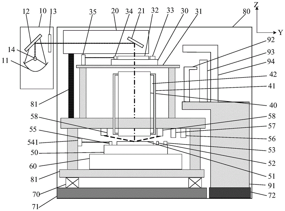
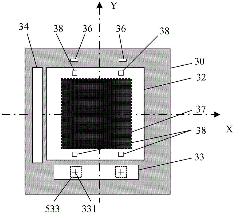
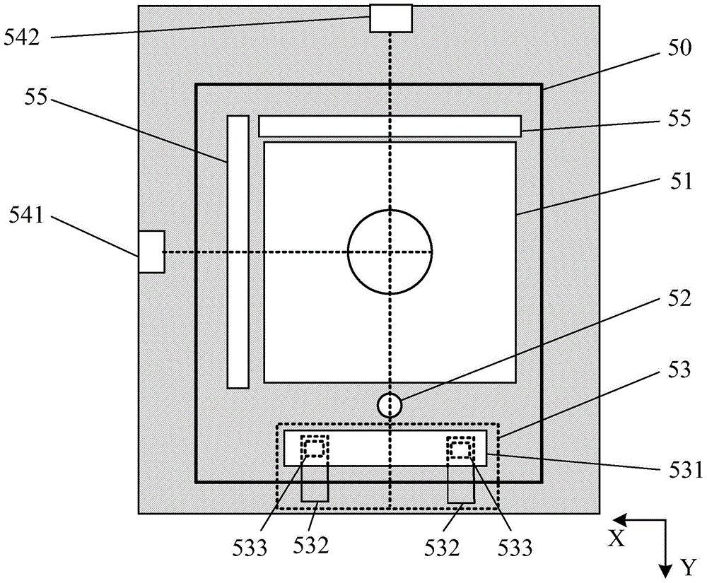
[0063] Such as figure 1 As shown, the projection exposure apparatus of the present invention includes: a lamp room system 10, an illumination system 20, a mask table 30, a projection objective lens 40, a work table 50, a work table carrying device 60, a shock absorbing device 70, a mask transmission device and a whole Machine protection 80.

[0064] The lamphouse system 10 is used to provide the exposure light source for the projection exposure device, and the illumination system 20 is used to adjust a...


PUM


Abstract

The present invention discloses a projection exposure apparatus, which comprises an illumination system, a mask table for bearing a mask, a projection object lens and a work-piece table for bearing a substrate, wherein the illumination system generates an illumination light beam to irradiate the mask, and the projection object lens projects the pattern on the mask onto the substrate surface. The projection exposure apparatus is characterized by further comprising a focusing leveling device, wherein the focusing leveling device generates a plurality of measurement points in the visual field of the projection object lens, and each measurement point comprises at least three measurement sub-light spots. According to the present invention, with the projection exposure apparatus, the production efficiency of the exposure equipment can be substantially improved, and the equipment use cost can be reduced; the screen with the large size can be obtained through the single exposure so as to reduce the complex process and the increased manufacturing cost caused by the splitting exposure; and the synchronous scanning technology, the image sensor technology and the exposure process focal plane real-time control technology are utilized to substantially increase the projection exposure apparatus overlay precision and the imaging quality and meet the low-cost and high-yield production requirements.

Description

technical field [0001] The invention relates to the field of photolithography machines, in particular to a projection exposure device. Background technique [0002] The circuit pattern drawn on the reticle is imaged on the surface of the substrate of the circuit that is coated with photosensitive material (such as photoresist) through a projection exposure device, and then the pattern is formed on the substrate of the circuit by etching and other processes. This light and shadow etching method is widely used in various fields, such as the field of integrated circuit manufacturing, the field of printed circuit board manufacturing and the field of manufacturing thin film transistor arrays of flat panel displays. [0003] The projection exposure device is to expose the circuit pattern on the reticle through an optical system such as a projection exposure lens, and project the circuit pattern on the substrate of the circuit at a certain magnification or reduction ratio. In recen...

Claims


Application Information

Patent Timeline
IPC IPC(8): G03F7/20G03F9/00
Inventor 周畅徐兵
Owner SHANGHAI MICRO ELECTRONICS EQUIP (GRP) CO LTD
Learn More