Dual-band circularly-polarized co-aperture microstrip antenna

A microstrip antenna, circularly polarized technology, applied to antennas, devices that make the antennas work in different bands at the same time, and radiating element structures, etc., can solve the unfavorable design of the feeding structure, common aperture design, and the axial ratio bandwidth is difficult to meet the requirements. , strong interference of different-band antennas, etc., to achieve the effect of mass production, elimination of inductance effects, and overall performance assurance

Inactive Publication Date: 2015-07-22
UNIV OF ELECTRONICS SCI & TECH OF CHINA
View PDF1 Cites 11 Cited by
  • Summary
  • Abstract
  • Description
  • Claims
  • Application Information

AI Technical Summary

Problems solved by technology

However, the traditional dual-frequency common-aperture microstrip antenna still has problems such as large size and strong interference from antennas in different frequency bands.
Especially in fields that require circular polarization of the ant

Method used


Image

  • Dual-band circularly-polarized co-aperture microstrip antenna
  • Dual-band circularly-polarized co-aperture microstrip antenna
  • Dual-band circularly-polarized co-aperture microstrip antenna

Examples


Embodiment

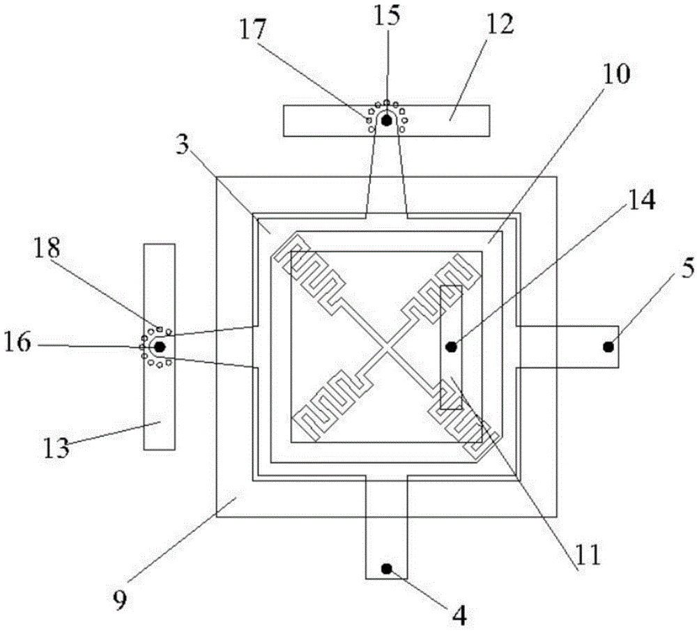
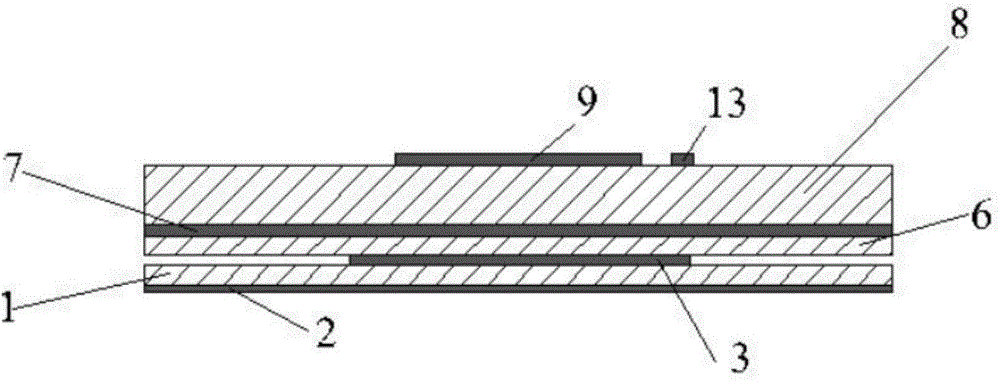
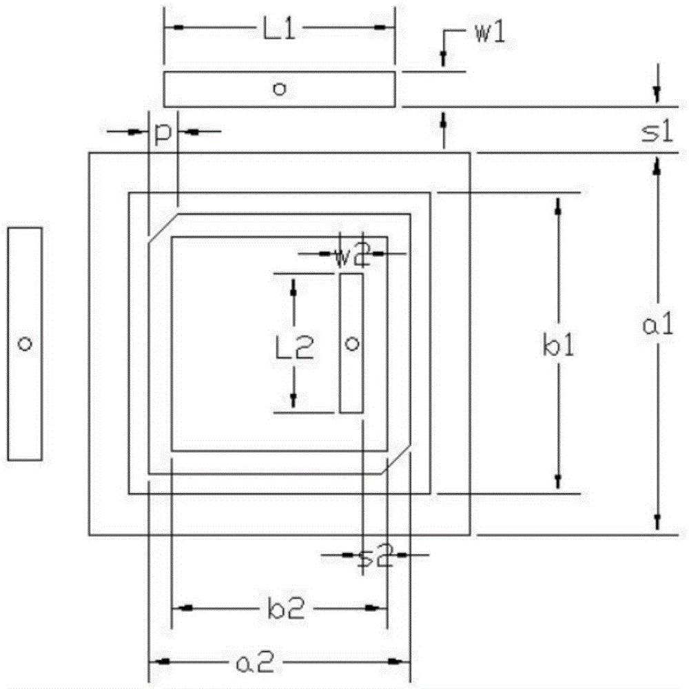
[0025] In this embodiment, the dual-band circularly polarized co-aperture microstrip antenna works in the K20GHz / Ka30GHz band. The first dielectric substrate 1 and the second dielectric substrate 6 adopt Rogers 5880 dielectric plates with a relative permittivity of 2.2 and a thickness of h1=h2=0.254mm, and the third dielectric substrate 8 adopts a relative permittivity of 2.2 and a thickness of h3=0.787mm Rogers 5880 dielectric plates, dimensions such as Figure 4 shown. The dimensions of the dual-band circularly polarized common-aperture microstrip antenna are as follows: image 3 As shown, the specific parameters are as follows: image 3 As shown, the specific dimensions of the antenna are: a1=3.3mm, b1=2.6mm, L1=2mm, w1=0.3mm, s1=0.4mm, h1=0.254mm, h2=0.254mm, h3=0.787mm, a2=2.25 mm, b2=1.85mm, L2=1mm, w2=0.2mm, s2=0.2mm, p=0.25mm.

[0026] The reflection coefficient of the dual-band circularly polarized common-aperture microstrip antenna in the K-band is as follows: ...


PUM

PropertyMeasurementUnit
Thicknessaaaaaaaaaa
Thicknessaaaaaaaaaa

Abstract

The invention discloses a dual-band circularly-polarized co-aperture microstrip antenna small in size and good in integrity. The dual-band circularly-polarized co-aperture microstrip antenna comprise a K-band square ring patch antenna and a Ka-band square ring patch antenna and is miniaturized; the two antennas of different frequencies are disposed in the same plane by coplanar nesting, thus sectional height of the antenna is decreased and the size of the antenna is reduced; additionally, by the use of a K-band coupler patch and the use of two-point feedback manner, the axial ratio performance of the K-band antenna is improved, and the axial ratio width is widened; a shield cavity composed of an array of metal through holes is arranged around metalized through holes, thus the metalized through holes and the shield cavity form a coaxial structure, inductive effect caused by the metalized through holes is eliminated and other possible radiations are shielded; therefore, overall performance of the antenna is guaranteed. The antenna is suitable for popularization and application in the technical field of antennas.

Description

technical field [0001] The invention relates to the technical field of antennas, in particular to a dual-band circularly polarized co-aperture microstrip antenna. Background technique [0002] The common-aperture antenna is an antenna array form that integrates antennas of different frequency bands and polarizations under the same aperture. The use of common-aperture antennas allows multiple antennas with different functions to be installed in the same space. Compared with separate placement of multiple antennas, this form greatly saves the space occupied and makes the entire communication system more compact. Common-aperture antennas can be designed using microstrip antennas, symmetrical array structures, helical antenna structures, parabolic and helical antennas, etc. However, the microstrip antenna has the advantages of light weight, convenient processing, low profile, and easy array formation. Therefore, most common-aperture antennas adopt a microstrip structure. At p...

Claims


Application Information

Patent Timeline
IPC IPC(8): H01Q13/08H01Q1/38H01Q1/36H01Q5/20
Inventor 杨鹏李岩闫飞
Owner UNIV OF ELECTRONICS SCI & TECH OF CHINA
Why Eureka
Try Eureka