
Dust removal device and method for oil gas during pulverized coal pyrolysis/retorting

A dust removal device, oil and gas technology, applied in gas dust removal and other directions, can solve the problems of poor separation effect of coke powder and oil and gas, unstable operation, low efficiency, etc., and achieve the effect of improving dust removal effect, reducing burden and avoiding damage.

Active Publication Date: 2015-07-29
SHAANXI COAL & CHEM IND GRP SHENMU TIANYUAN CHEM IND +1
View PDF7 Cites 17 Cited by
  • Summary
  • Abstract
  • Description
  • Claims
  • Application Information

AI Technical Summary

Problems solved by technology

[0005] For this reason, the technical problem to be solved by the present invention lies in the problems such as poor separation effect of coke powder and oil gas, low efficiency and unstable operation in the process of filtering and separating pulverized coal pyrolysis / carbonization oil gas in the dusty oil gas dedusting device in the prior art, and then Provide a pulverized coal pyrolysis / carbonization oil and gas dedusting device with ideal separation effect, stable and safe operation and high efficiency

Method used


Image

  • Dust removal device and method for oil gas during pulverized coal pyrolysis/retorting
  • Dust removal device and method for oil gas during pulverized coal pyrolysis/retorting

Examples


Embodiment Construction

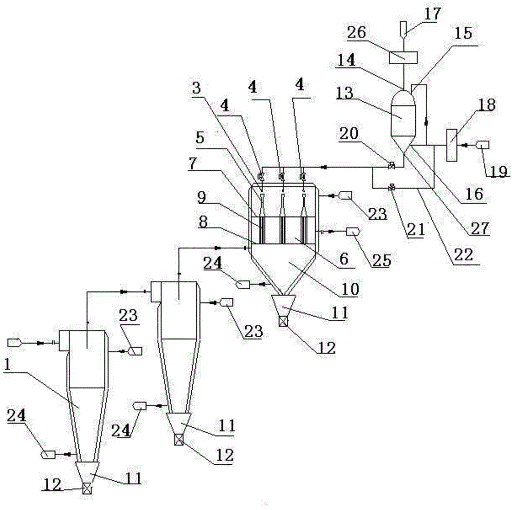
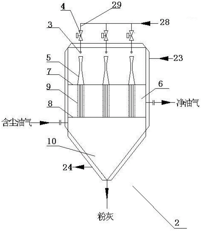
[0036] Such as Figure 1-2 The shown dust removal device for pulverized coal pyrolysis / carbonization oil and gas includes sequentially connected, dust removal pretreatment units, communicated with high-temperature oil and gas pipelines, and includes at least two stages of cyclone separators 1 in series for heat treatment of pulverized coal. Decomposition / carbonization of oil and gas for coarse dust removal; oil and gas filter 2, the oil and gas filter 2 is a closed tank, the interior is arranged in sequence from top to bottom, and the nozzle 3 is set on the top of the tank, and is imported through the high-temperature sand-containing gas The pipeline 29 communicates with the outside of the tank body. The high-temperature sand-containing gas inlet pipeline 29 is provided with a pulse control valve 4; the venturi tube 5 is vertically arranged below the nozzle 3; the clean oil and gas chamber 6 is perpendicular to the The Venturi tube 5 is set, and the inside is provided with a h...


PUM


Abstract

The invention provides a dust removal device and method for oil gas during pulverized coal pyrolysis / retorting. The device comprises a dust removal pretreatment unit, an oil gas filter and a sand-blasting tank which are sequentially connected, wherein the dust removal pretreatment unit comprises at least two stages of cyclone separators connected in series; the oil gas filter adopts a closed tank, and nozzles, venture tubes, an oil gas purification chamber, a gas collecting chamber and dust hoppers are arranged in the oil gas filer from top to bottom sequentially; the nozzles are arranged at the top of the tank and communicated with the outside; the venture tubes are correspondingly and perpendicularly arranged below the nozzles; the oil gas purification chamber is perpendicular to the venture tubes and provided with hollow filter element groups inside, and the hollow filter element groups are in sealing connection with an upper tube plate and a lower tube plate of the oil gas purification chamber; the gas collecting chamber is coaxially communicated with filter elements; dust valves are arranged at the lower ends of the dust hoppers; the sand-blasting tank is a closed tank, a sand inlet is formed in the top and communicated with a sand pipeline inlet through a sand preheater, gas inlets are formed in the top and in the lower side part respectively and are communicated with a reverse blowing gas pipeline inlet through a reverse blowing gas preheater, and a sand outlet is formed in the bottom and communicated with the oil gas filter. The problems of poor oil gas dust removal effect, low efficiency, instable operation and the like of an existing device are solved.

Description

technical field [0001] The invention belongs to the technical field of high-temperature dry dedusting of dusty oil and gas in coal chemical industry, and in particular relates to a dedusting device and a dedusting method for high-temperature oil and gas produced in the process of producing coal tar by pyrolysis / carbonization of pulverized coal. Background technique [0002] In recent years, with the improvement of coal mining mechanization, the proportion of pulverized coal is increasing, and the market price of pulverized coal is only one-third of the price of lump coal. If pulverized coal is used as raw material to produce chemical products, the advantages are obvious, but pulverized coal is hot There is still no effective separation means for the separation technology of oil gas and coke powder in the process of hydrolysis or dry distillation, which seriously restricts the development of this industry. [0003] At present, the separation methods of coke powder and oil and...

Claims


Application Information

Patent Timeline
IPC IPC(8): C10K1/02
Inventor 王守峰山秀丽李锦涛常景泉王淑岩贺鑫平李万飞吕子胜吴莹莹
Owner SHAANXI COAL & CHEM IND GRP SHENMU TIANYUAN CHEM IND
Learn More