Hydraulic rotating jet flow blockage remover

A technology of hydraulic rotary and block remover, which is applied in drilling equipment, wellbore/well components, earth-moving drilling, etc. Simple structure and concentrated energy

Active Publication Date: 2015-07-29
XI'AN PETROLEUM UNIVERSITY
View PDF6 Cites 4 Cited by
  • Summary
  • Abstract
  • Description
  • Claims
  • Application Information

AI Technical Summary

Problems solved by technology

The current plugging removal technology has the following three types: 1. In the past, the ground mechanical lifting device was used to lift and lower the pipe string to achieve cleaning within a certain range of oil layers, but automatic reciprocating motion could not be realized; 2. The use of volumetric motors, milling cutters, Impact hammer with milling cutter or pure liquid jet cleaning, but milling cutters and similar cutting tools will endanger the integrity of the pipeline during operation; Injection well jet plugging device that can perform well cleaning and pulse treatment on the oil layer, all of which are destructive to the wellbore and formation conditions

Method used


Image

  • Hydraulic rotating jet flow blockage remover
  • Hydraulic rotating jet flow blockage remover
  • Hydraulic rotating jet flow blockage remover

Examples


Embodiment Construction

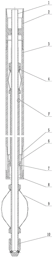
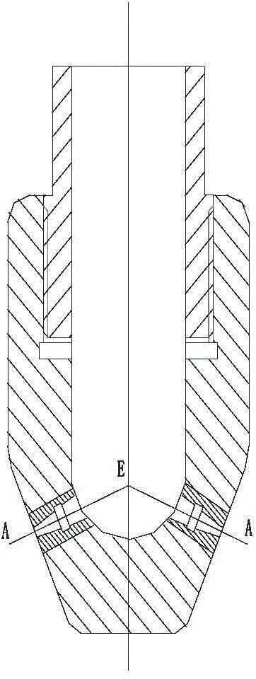
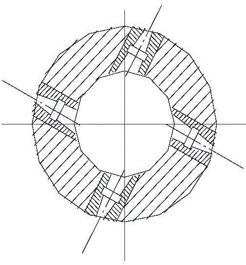
[0026] Below in conjunction with accompanying drawing, the present invention is described in further detail:

[0027] see Figure 1 to Figure 4 , a hydraulic rotary jet block remover, comprising a screw rod 1, the middle part of the screw rod 1 is a threaded section, the length of the threaded section is 1-9m, the threaded section is provided with a left-handed thread and a right-handed thread, and the left-handed thread and the right-handed thread The starting position and the ending position are the same, but the direction of the two is opposite. The lead angle of the left-handed thread and the right-handed thread are both 15°. The upper centralizer 4 is also sleeved on the screw 1, and the upper centralizer 4 is located on the upper side of the thread section. , both ends of the upper centralizer 4 are fixed on the screw rod 1 through a circlip, the upper centralizer 4 and the outer side of the threaded section are covered with a casing 3, the upper end of the casing 3 is c...


PUM


Abstract

The invention discloses a hydraulic rotating jet flow blockage remover, which comprises a screw rod, wherein the middle part of the screw rod is a threaded section, left-hand screw threads and right-hand screw threads are arranged on the threaded section, an upper centralizer is also arranged on the screw rod, the upper centralizer is positioned at the upper side of the threaded section, a case is arranged at the outer sides of the threaded section and the upper centralizer in a sleeving way, the upper end of the case is connected with a short joint, the lower end of the case is connected with a connecting pipe, the lower end of the connecting pipe is connected with a connecting end cover, a base is arranged in the connecting pipe, two pins are fixedly arranged on the base, and are respectively inserted into the left-hand screw threads and the right-hand screw threads, in addition, the position difference of the two pins is 1.5 thread pitches, the bottom of the screw rod is connected with a rotating spray head, and a lower centralizer is arranged between the rotating spray head and the connecting end cover. The hydraulic rotating jet flow blockage remover has the advantages that the structure is simple, in addition, the jet hole section of the whole oil layer can be thoroughly cleaned, the cleaning quality is high, no damage occurs, the cleaning speed is high, and the efficiency is high.

Description

technical field [0001] The invention relates to an underground block removal device, in particular to a hydraulic rotary jet block removal device. Background technique [0002] In high-water-cut late-stage oilfields and heavy-oil low-permeability oilfields, due to pollution and mechanical impurity precipitation during drilling, well completion, downhole operations, and long-term oil production and water injection, the pore channels in the near-wellbore area are very blocked, resulting in oil production of oil-water wells. And the water injection volume drops or even stops production. The current plugging removal technology has the following three types: 1. In the past, the ground mechanical lifting device was used to lift and lower the pipe string to achieve cleaning within a certain range of oil layers, but automatic reciprocating motion could not be realized; 2. The use of volumetric motors, milling cutters, Impact hammer with milling cutter or pure liquid jet cleaning, b...

Claims


Application Information

Patent Timeline
Patent Type & Authority Applications(China)
IPC IPC(8): E21B21/00E21B17/10
CPCE21B17/10E21B21/00
Inventor 韩成才苗亮朱林王丽春张高媛
Owner XI'AN PETROLEUM UNIVERSITY
Why Eureka
Try Eureka