An acousto-optic real-time signal analyzer based on asynchronous detection

A real-time signal and analyzer technology, applied in the field of optoelectronics, can solve problems such as increased requirements, fuzzy time resolution, high transmission power consumption, etc., and achieve the effects of realizing transient signal monitoring, solving data redundancy, and large dynamic performance

Active Publication Date: 2018-02-02
CHINA ELECTRONICS TECH GRP NO 26 RES INST
View PDF5 Cites 0 Cited by
  • Summary
  • Abstract
  • Description
  • Claims
  • Application Information

AI Technical Summary

Problems solved by technology

At present, in the field of digital technology, algorithm theories such as short-time Fourier transform, Winger-Ville distribution, and wavelet transform are used to analyze transient signals, but they all have a common shortcoming: lack of adaptability, and it is easy to deal with irregular signals. cause aliasing
However, this kind of acousto-optic spectrum analyzer uses a charge-coupled device (CCD) with a very slow reading speed in the photoelectric conversion link, which outputs signals accumulated over a period of time pixel by pixel, and can only detect the presence of What frequency does not specify the specific moment when these frequencies exist, that is, the instantaneous frequency cannot be expressed, and there is ambiguity in time resolution
[0004] At present, the increasingly complex electromagnetic signal environment urgently needs a signal processing system with instantaneous large bandwidth and high dynamics, which can realize real time-frequency analysis. At the same time, this means that the use of digital analysis technology will generate a huge amount of output data. Generate higher transmission power consumption, increase the requirements for the number of channels, memory and computing processing system, and these requirements are basically infeasible for the current device level

Method used


Image

  • An acousto-optic real-time signal analyzer based on asynchronous detection
  • An acousto-optic real-time signal analyzer based on asynchronous detection
  • An acousto-optic real-time signal analyzer based on asynchronous detection

Examples


Embodiment Construction

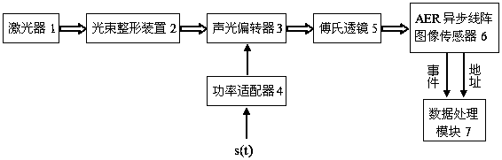
[0019] see figure 1 , as can be seen from the figure, the present invention includes a laser 1, a beam shaping device 2, an acousto-optic deflector 3, a power adapter 4, a Fourier lens 5, an AER asynchronous line array image sensor 6 and a data processing module 7. In the above, the optical components laser 1, beam shaping device 2, acousto-optic deflector 3, Fourier lens 5, and AER asynchronous line array image sensor 6 are sequentially arranged on the same optical axis to establish an optical path system. The electrical signal s(t) to be tested is first input into the power adapter 4 to adjust its amplitude variation range to match the best driving power range of the acousto-optic deflector 3 . The beam generated by the laser 1 becomes a flat beam (matching the effective aperture of the AOD 3) after being passed through the beam shaping device 2, and is incident on the light window of the AOD 3, passing through the AOD 3 from the aperture . At this time, according to the w...


PUM


Abstract

The invention discloses an acousto-optic real-time signal analyzer based on asynchronous detection, which includes a laser, a beam shaping device, an acousto-optic deflector, a power adapter, a Fourier lens, an AER asynchronous line array image sensor and a data processing module; the AER asynchronous line The output of the array image sensor is connected to the data processing module; each diffracted beam output by the acousto-optic deflector completes the spatial Fourier transform through the Fourier lens, and is incident on the pixel of the AER asynchronous linear array image sensor; the data processing module controls the AER asynchronous linear array The spatial position of each pixel output by the image sensor and the magnitude of the photocurrent induced by the pixel are processed, converted into time-frequency domain parameters corresponding to the measured signal, and stored and displayed. The invention has large bandwidth, high sensitivity and large dynamic performance. High time precision, effectively realize transient signal monitoring; fundamentally solve the problem of data redundancy; can process parallel signals in real time, and have strong adaptability to different types of signals.

Description

technical field [0001] The invention relates to signal time-frequency analysis technology, in particular to an acousto-optic real-time signal analyzer based on asynchronous detection, which belongs to the field of optoelectronic technology. Background technique [0002] With the advancement of science and technology, the signals that people need to detect develop from stable, regular, and predictable to unpredictable, transient, and increasingly complex. In modern signal processing methods, time and frequency are the two most important physical quantities to describe signals, and there is a close relationship between the time domain and frequency domain of signals. The time-frequency analysis method, which maps a one-dimensional time signal to a two-dimensional time-frequency plane, describes and observes the signal comprehensively and in detail in the time-frequency domain, has recently been more and more widely used. The traditional swept frequency (superheterodyne) spect...

Claims


Application Information

Patent Timeline
Patent Type & Authority Patents(China)
IPC IPC(8): G01R23/17
Inventor 吴冉张泽红陈永峰谢强
Owner CHINA ELECTRONICS TECH GRP NO 26 RES INST
Why Eureka
Try Eureka