Multi-path signal unipolar square wave modulated single-path synchronous collection device and method
A synchronous acquisition and multi-channel signal technology, applied in the field of signal measurement, can solve the problems of switching noise, high system power consumption, large circuit size, etc., and achieve the effect of simple circuit, accurate measurement and low cost
- Summary
- Abstract
- Description
- Claims
- Application Information
AI Technical Summary
Problems solved by technology
Method used
Image
Examples
Embodiment 1
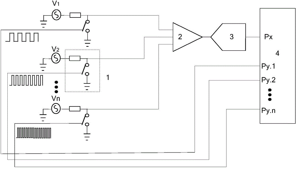
[0024] A single-channel synchronous acquisition device for multi-channel signal unipolar square wave modulation, see figure 1 , the single-channel synchronous acquisition device includes: at least two switch circuits 1, an addition operation circuit 2, a single-channel analog-to-digital converter 3 and a microprocessor 4,
[0025] The microprocessor 4 outputs square waves with different frequencies and a ratio of 2 times. The square waves control the on-off of at least two switch circuits 1, and N (N>=2) measured signals pass through the switch circuit 1 (the switch circuit 1 Composed of resistors and analog switches), the switch circuit 1 is used to realize chopping amplitude modulation. The amplitude modulated signals of different frequencies are added by the addition operation circuit 2, and then converted by the single-channel analog-to-digital converter 3 to obtain a digital signal. The microprocessor 4 processes the digital signals and demodulates each measured signal. ...
Embodiment 2
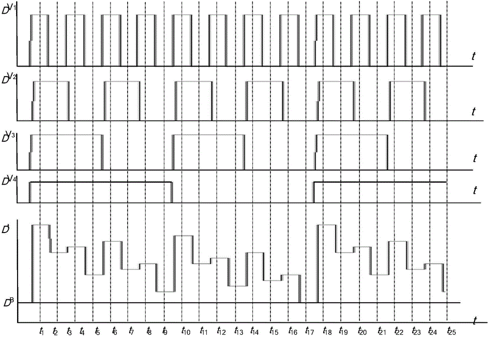
[0028] A single-channel synchronous acquisition method for multi-channel signal unipolar square wave modulation, see figure 2 and image 3 , the method includes the following steps:
[0029] 101: the mixed signal is converted into a digital signal by the single-channel analog-to-digital converter 3 and sent to the microprocessor 1;
[0030] 102: The microprocessor processes the digital signal, and demodulates each measured signal.
[0031] For the sake of simplicity, take 4 frequency square waves to drive the switch circuit 2 and collect 4 measured signals as an example. Assume that the measured signal V 1 , V 2 , V 3 and V 4 The driving square wave frequencies corresponding to the switching circuit 1 are 8f, 4f, 2f and f respectively.
[0032] Assume that the sampling frequency of the single-channel ADC 3 is f S , and f S =16f, and guaranteed at V 1 Sampling between high and low levels of the signal.
[0033] digital signal sequence It can be expressed as:
[00...
PUM
 Abstract
Description
Claims
Application Information
 - R&D
- Intellectual Property
- Life Sciences
- Materials
- Tech Scout
- Unparalleled Data Quality
- Higher Quality Content
- 60% Fewer Hallucinations
Browse by: Latest US Patents, China's latest patents, Technical Efficacy Thesaurus, Application Domain, Technology Topic, Popular Technical Reports.
© 2025 PatSnap. All rights reserved.Legal|Privacy policy|Modern Slavery Act Transparency Statement|Sitemap|About US| Contact US: help@patsnap.com


