Double-handstand turning center lathe

A turning center and vertical machining technology, applied in turning equipment, turning equipment, metal processing equipment, etc., can solve the problems of difficulty in ensuring coaxiality requirements and dimensional accuracy, large number of machine tools and operators, and long auxiliary time consumption. Achieve the effect of saving auxiliary loading and unloading time, saving human resources, improving precision and product quality

Active Publication Date: 2015-08-05
JINAN FIRST MACHINE TOOL GROUP
View PDF10 Cites 2 Cited by
  • Summary
  • Abstract
  • Description
  • Claims
  • Application Information

AI Technical Summary

Problems solved by technology

[0004] 1. The process time does not match. Generally speaking, the turning time of CNC vertical lathe is twice that of the drilling and tapping time of the machining center. To achieve the matching effect, the number of CNC vertical lathes must be doubled;
[0005] 2. After several times of clamping, the bearing holes at both ends turn around, and the processing is not easy to ensure the coaxiality requirements and dimensional accuracy;
[0006] 3. The iron filings are not easy to discharge when the CNC vertical lathe is turning the inner hole, and it is easy to cause the iron filings to scratch the surface of the finished inner hole and damage the machining accuracy;
[0007] 4. The number of transfer processes is large, and the auxiliary time is long, which greatly affects the production efficiency;
[0008] 5. A large number of machine tools and operators are required, which wastes human resources and increases manufacturing costs

Method used


Image

  • Double-handstand turning center lathe
  • Double-handstand turning center lathe
  • Double-handstand turning center lathe

Examples


Embodiment Construction

[0032] The technical solutions in the embodiments of the present invention are clearly and completely described below in conjunction with the drawings in the embodiments of the present invention.

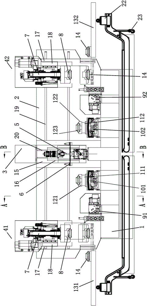
[0033] combine Figure 3 to Figure 5 , a kind of double inverted turning center is vertically added, comprises bed base 1, is provided with column 2 above the rear part of bed base 1, and the front end face of described column 2 is provided with horizontal column guide rail 19 in the left and right direction, namely X-axis direction, and column 2 An electrical box 21 is provided on the rear end, and a vertical machining center that moves horizontally and laterally along the column guide rail is provided in the middle of the horizontal column guide rail, referred to as the vertical machining center 3, and on both sides of the vertical column guide rail, there are respectively a set of vertical machining centers that move horizontally and laterally along the column guide rail. The inv...


PUM


Abstract

The invention discloses a double-handstand turning center lathe. The double-handstand turning center lathe comprises a bed base; the bed base is provided with a standing column; the standing column is provided with a standing column guide rail; the standing column guide rail is connected with the lathe and a left-right handstand turning center; the lathe comprises a lathe carriage, a lathe sliding plate, a left work bench, and a right work bench; the lathe carriage is matched with the lathe sliding plate; the lathe sliding plate is provided with a lathe main shaft; a lathe tool changer at the front side of the lower part of the lathe main shaft is connected with the base; the left-right handstand turning center comprises a handstand turning center carriage, a handstand turning center sliding plate, and a handstand turning center main shaft; the lower part of the handstand turning center main shaft is connected with a handstand chuck; the base between the lathe main shaft and the handstand turning center main shaft is provided with a work bench base; the work bench is provided with a left clamping fixture; and the bed base is provided with a turning head. The double-handstand turning center lathe is capable of achieving the optimal matching of the turning and lathe time during the processing of the disc parts, saving the labor, reducing the manufacturing cost, and ensuring the precision and quality of the part production, the whole processing time is the shortest, and the production efficiency is high.

Description

technical field [0001] The invention relates to the technical field of numerical control machining centers, in particular to a double inverted turning center vertical machining. Background technique [0002] In the processing of various disc parts such as automobiles, such as bearing housing parts, see figure 1 , figure 2 , its size and outer diameter are mostly within a certain size range, such as between φ200mm-φ350mm, such parts often require precision turning on the internal hole system and both ends, and some threaded holes are distributed on one end surface of the plate edge, and the other Some counterbores and through holes are distributed on the end face, and the diameters of these threaded holes, counterbores and through holes are also different, which brings inconvenience to the processing of such parts. [0003] In the prior art, the process route for processing this kind of parts is generally: first use a CNC vertical lathe to turn the inner hole system, outer...

Claims


Application Information

Patent Timeline
Patent Type & Authority Applications(China)
IPC IPC(8): B23B9/12
CPCB23B9/08
Inventor 朱宇翔陈树德李华房超
Owner JINAN FIRST MACHINE TOOL GROUP
Why Eureka
Try Eureka