Centralized optical fiber end grinding and cleaning device

A cleaning device and optical fiber technology, applied in the field of optical fiber equipment, can solve problems such as injury to optical fiber equipment and operators, environmental dust pollution in the workplace, low efficiency of optical fiber polishing, etc., to avoid noise and dust pollution, and improve cleanliness and smoothness , Improve the effect of surface cleanliness and smoothness

Active Publication Date: 2015-08-05
南通鸿图健康科技有限公司
View PDF7 Cites 2 Cited by
  • Summary
  • Abstract
  • Description
  • Claims
  • Application Information

AI Technical Summary

Problems solved by technology

[0002] At present, in the process of optical fiber processing, especially in the processing of optical fiber end coating, in order to improve the communication quality of optical fiber products, the smoothness and cleanliness of the surface of the optical fiber end must be processed, and this process is currently being processed At the same time, it is mainly through manual grinding and cleaning by the operator with the help of grinding equipment, which on the one hand causes the work efficiency of optical fiber grinding to be low, labor-intensive, and the quality is relatively poor and the quality fluctuation is extremely poor. On the other hand, it will also cause It will cause serious pollution and dust pollution to the workplace environment, and cause serious damage to optical fiber equipment and operators. Therefore, in view of this situation, it is urgent to develop a new type of optical fiber polishing device to meet the needs of actual use.

Method used


Image

  • Centralized optical fiber end grinding and cleaning device

Examples


Embodiment Construction

[0011] In order to make the technical means, creative features, goals and effects achieved by the present invention easy to understand, the present invention will be further described below in conjunction with specific embodiments.

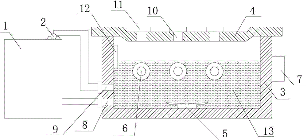
[0012] Such as figure 1 The centralized grinding and cleaning device for optical fiber ends includes a circulating water tank 1 and a grinding chamber. The circulating water tank 1 communicates with the grinding chamber through a circulating pump 2. The grinding chamber includes a grinding tank 3, an optical fiber positioning frame 4, and a driving water wheel. 5. The grinding roller 6 and the driving device 7, wherein the cross section of the grinding tank 3 is "concave" shape, the bottom of which is provided with a circulating water inlet 8 and a water outlet 9, and the driving water wheel 5 is located at the centerline of the inner surface of the bottom of the grinding tank 3, At least one grinding roller 6 is located below the liquid level of ...


PUM


Abstract

The invention relates to a centralized optical fiber end grinding and cleaning device which comprises a circulating water tank and a grinding chamber. The circulating water tank is communicated with the grinding chamber through a circulating pump, the grinding chamber comprises a grinding groove, an optical fiber positioning frame, a driving water wheel, at least one grinding roller and a driving device, wherein the cross section of the grinding groove is in a shape of a Chinese character 'ao', the driving water wheel is located at the bottom of the grinding groove, the grinding roller is located in the grinding groove and located under the circulating water level, the optical fiber positioning frame is embedded into the upper end face of the grinding groove, at least four optical fiber positioning holes are distributed in the optical fiber positioning frame in a rectangular array mode, optical fiber positioning clamps are additionally arranged at the positions of the optical fiber positioning holes, and the driving device is located outside the grinding grooves and is connected with the driving water wheel and the grinding rollers respectively. In addition, the centralized optical fiber end grinding and cleaning device has grinding and cleaning functions, the surface cleanness and finish degree of optical fiber ends can be greatly improved, noise and dust pollution easily caused in the optical fiber end grinding process is effectively avoided, and optical fiber machining operation environment is greatly improved.

Description

technical field [0001] The invention relates to a centralized grinding and cleaning device for optical fiber ends, which belongs to the technical field of optical fiber equipment. Background technique [0002] At present, in the process of optical fiber processing, especially in the processing of optical fiber end coating, in order to improve the communication quality of optical fiber products, the smoothness and cleanliness of the surface of the optical fiber end must be processed, and this process is currently being processed At the same time, it is mainly through manual grinding and cleaning by the operator with the help of grinding equipment, which on the one hand causes the work efficiency of optical fiber grinding to be low, labor-intensive, and the quality is relatively poor and the quality fluctuation is extremely poor. On the other hand, it will also cause It causes serious pollution and dust pollution to the workplace environment, and causes serious damage to optic...

Claims


Application Information

Patent Timeline
Patent Type & Authority Applications(China)
IPC IPC(8): B24B37/10B24B37/30B24B7/16B24B41/06
CPCB24B7/16B24B37/10B24B37/30B24B41/06
Inventor 薛文英
Owner 南通鸿图健康科技有限公司
Why Eureka
Try Eureka