Magnetic coupling resonant wireless power transmission device based on low frequency pwm rectifier

A rectifier and resonant technology, which is applied in the field of magnetic coupling resonant wireless power transmission devices, can solve the problems of reducing the operating frequency of power switching, uncertainty of wireless transmission distance, and affecting use.

Active Publication Date: 2017-02-22
CHINA JILIANG UNIV
View PDF5 Cites 0 Cited by
  • Summary
  • Abstract
  • Description
  • Claims
  • Application Information

AI Technical Summary

Problems solved by technology

At present, the uncontrollable diode bridge rectification is usually used to obtain the DC output voltage, but due to the uncertainty of the wireless transmission distance, the mutual inductance between the transmitting circuit and the receiving circuit coupling resonant coil changes, so that the amplitude of the DC output voltage cannot be kept constant. , affecting the use of
Therefore, a magnetically coupled resonant wireless power transmission device based on a low-frequency PWM rectifier is proposed here. It uses the double induced voltage detection coil installed on the side of the receiving circuit to detect the induced voltage of the resonant coil of the receiving circuit, and uses the induced voltage as the receiving circuit The reference quantity of tuning control, at the same time, the half-bridge PWM rectifier is used to realize the resonance control of the receiving circuit and the output of constant voltage, and at the same time adjust the frequency of the high-frequency power supply of the transmitting circuit to realize the resonance of the transmitting circuit. When the frequency of the high-frequency power changes, the double induction The frequency of the induced voltage of the resonant coil of the receiving circuit detected by the voltage detection coil changes synchronously, so the half-bridge PWM rectifier can track the change of the high-frequency power supply frequency and realize the resonance control of the receiving circuit, and the half-bridge PWM rectifier adopts low-frequency pulse width modulation technology, which reduces the requirements for the operating frequency of the power switch. At present, there are no patents or other literature reports for such a magnetic coupling resonant wireless power transmission device.

Method used


Image

  • Magnetic coupling resonant wireless power transmission device based on low frequency pwm rectifier
  • Magnetic coupling resonant wireless power transmission device based on low frequency pwm rectifier
  • Magnetic coupling resonant wireless power transmission device based on low frequency pwm rectifier

Examples


Embodiment Construction

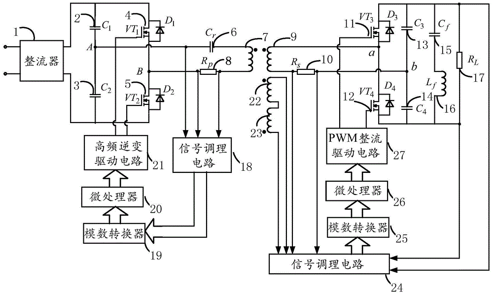
[0051] A magnetically coupled resonant wireless energy transmission device based on a low-frequency PWM rectifier proposed by the present invention, its embodiment is as follows figure 1 , figure 2 with image 3As shown, it includes a rectifier 1, a first voltage stabilizing capacitor 2, a second voltage stabilizing capacitor 3, a first inverter power switch 4, a second inverter power switch 5, a transmitting circuit resonant capacitor 6, and a transmitting circuit resonant coil 7, Transmitting circuit current sampling resistor 8, receiving circuit resonant coil 9, receiving circuit current sampling resistor 10, first rectifying power switch 11, second rectifying power switch 12, third stabilizing capacitor 13, fourth stabilizing capacitor 14, resonance filter Capacitor 15, resonant filter inductor 16, load resistor 17, signal conditioning circuit 18 at the transmitting end, analog-to-digital converter 19 at the transmitting end, microprocessor 20 at the transmitting end, hi...


PUM


Abstract

The invention discloses a magnetic coupling resonant wireless electric energy transmission device based on a low frequency PWM rectifier. The device comprises a rectifier, a voltage stabilizing capacitor, an inverter power switch, an emission circuit resonant capacitor, an emission circuit resonant coil, an emission circuit current sampling resistor, a receiving circuit resonant coil, a receiving circuit current sampling resistor, a rectifier power switch, a resonant filter capacitor, a resonant filter inductor, a load resistor, a transmitting end signal conditioning circuit, a transmitting end analog to digital converter, a transmitting end microprocessor, a transmitting end high frequency inverter driving circuit, an induction voltage detection coil, a receiving end signal conditioning circuit, a receiving end analog to digital converter, a receiving end microprocessor and a PWM rectifier driving circuit. According to the device, the resonance of an emission loop is ensured, the tracking of transmitting end working frequency, the resonance of a receiving circuit and the constant output of load voltage are realized, the requirement of working frequency by a power switch device is greatly reduced, and a space is provided for the device to raise power supply working frequency.

Description

technical field [0001] The invention belongs to the technical field of wireless power transmission, and in particular relates to a magnetic coupling resonant wireless power transmission device, in particular to a magnetic coupling resonant wireless power transmission device based on a low-frequency PWM rectifier. Background technique [0002] Wireless power transmission is a flexible and convenient power transmission method. It overcomes the problems of contact wear and easy generation of electric sparks in the traditional wire transmission method, and improves the safety and reliability of the system. At present, wireless power transmission is mainly divided into three types of technologies: radiation, electromagnetic induction and magnetic coupling resonance. Among them, magnetic coupling resonance wireless power transmission technology has obvious advantages when both transmission distance and transmission power need to be considered. [0003] The ideal magnetic coupling ...

Claims


Application Information

Patent Timeline
Patent Type & Authority Patents(China)
IPC IPC(8): H02J50/12H02M3/335
CPCY02B70/10
Inventor 谢岳潘伟玲
Owner CHINA JILIANG UNIV
Why Eureka
Try Eureka