
A dual-band surface plasmon resonator
A plasma and resonant cavity technology, applied in discharge tubes, electrical components, circuits, etc., can solve problems such as inability to excite surface plasmon multi-frequency resonance, and achieve good development prospects, easy manufacturing, and a wide range of product applications.
- Summary
- Abstract
- Description
- Claims
- Application Information
AI Technical Summary
Problems solved by technology
Method used
Image

Examples
Embodiment 1
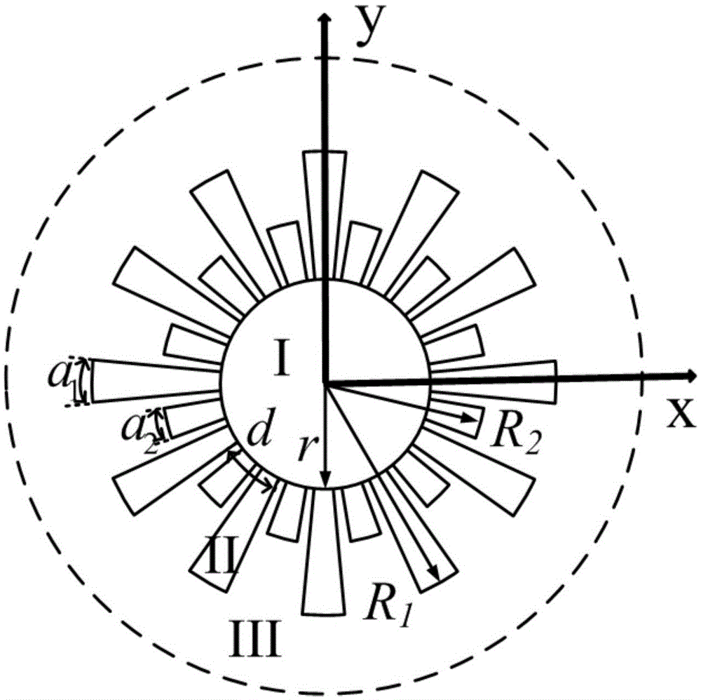
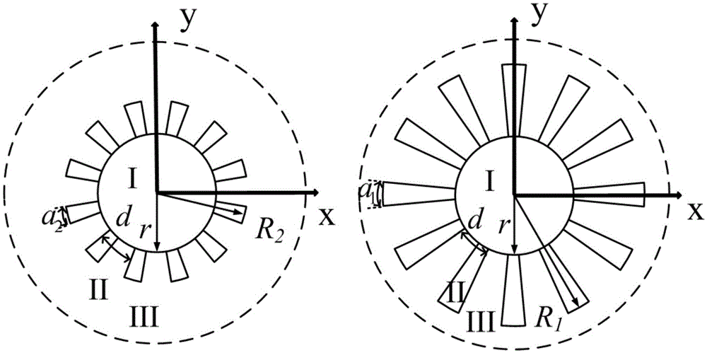
[0017] As shown in Figure 1(a), the basic structure of the resonant cavity is a metal cylinder with a certain thickness that is closed at both ends (both ends are closed with a circular metal plate that matches the cross-sectional area of the metal cylinder). The inner diameter of the cross-section is r, and the inner wall is provided with two kinds of axial grooves uniformly distributed along the circumference. The central angles corresponding to each groove are equal, and the cross-section is fan-shaped. The two axial grooves have different depths R 1 -r (deep groove) and R 2 -r (shallow groove), R 1 >R 2 , R 1 , R 2 represent the radii at the maximum radians of the two grooves respectively. Generally speaking, there is an approximate formula for the asymptotic frequency of the surface plasmon structure, f a =c / (4hn g ), where c is the speed of light, h=R 1 (2)-r is the depth of the groove, n g Represents the refractive index of the material in the trench, from whi...
Embodiment 2
[0019] Taking the resonant cavity shown in Figure 1(a) as an example, the radius r=1.33 mm, and the radius at the maximum radian of the groove is R 1 = 5 mm, R 2 =3.33 mm, different groove depths determine the different resonant frequencies of the structure. The dielectric constant of the filling dielectric material is equal to 25, and the filling of the dielectric material can reduce the resonant frequency of the resonant cavity. According to the equivalent medium theory, the more the number of periods is set, the better the effect, but the increase in the number of grooves will cause inconvenience in processing. Here we make a compromise by periodically distributing N=120 grooves along the circumferential direction, in which deep grooves and shallow grooves are respectively There are 60 of them, and they are staggered and evenly distributed.
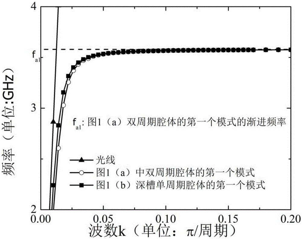
[0020] According to the second embodiment, the electromagnetic simulation software can be used to obtain the dispersion curve as sh...
PUM
 Abstract
Description
Claims
Application Information