

Catalytic cracking reactivator test simulation method and device
A technology of experimental simulation and catalytic cracking, which is applied in the field of experimental simulation methods and devices of catalytic cracking regenerators, and can solve problems such as unpredictable and guiding industrial processes
- Summary
- Abstract
- Description
- Claims
- Application Information
AI Technical Summary
Problems solved by technology
Method used
Image

Examples
Embodiment 1
[0076] Embodiment 1: the mensuration of the carbon content of the raw catalyst in the bubbling bed fluidized state
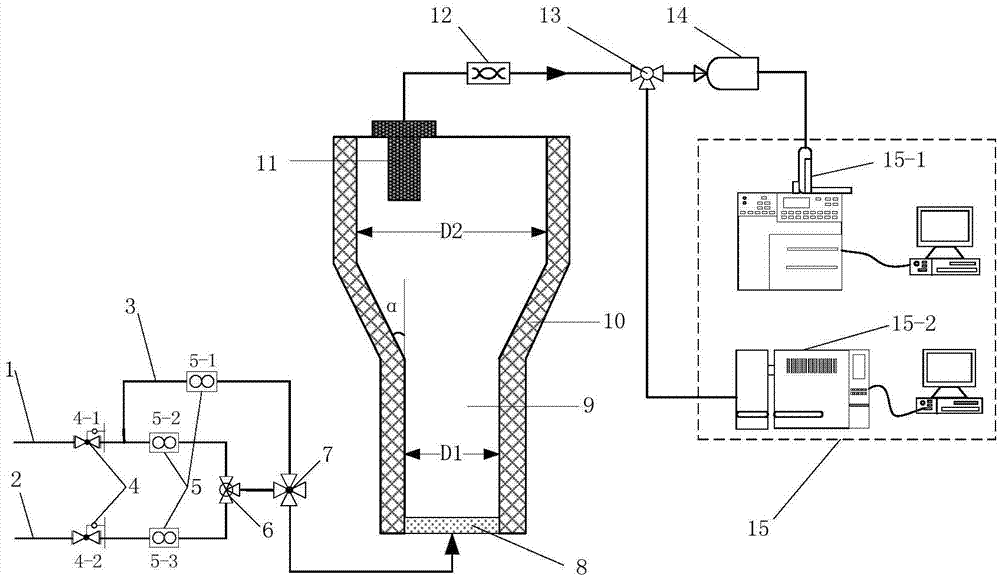
[0077] Such as figure 1As shown, the gas path (1) uses helium, and the gas path (2) uses air. The volume percentage of oxygen in the mixed gas is controlled by the mass flowmeters on the two gas paths to be 1%, and the total gas flow rate is 1.5L. / min. Reaction tube (9) adopts quartz glass material, and its lower cylinder diameter D1 is 35mm, height-diameter ratio is 100, and upper cylinder diameter D2 is 210mm, height-diameter ratio is 10, D2: D1=6; The included angle α is 60°. At this time, the superficial gas velocity of the lower part of the reaction tube is 0.1m / s, and the superficial gas velocity of the upper part of the reaction tube is 0.01m / s. The gas distributor adopts an orifice plate with an opening diameter of 0.5mm and an opening rate of 9 pcs / cm 2 ; The gas-solid separator adopts a metal sintered plate with an aperture of 10nm. The outside of...
Embodiment 2
[0081] Embodiment 2: the mensuration of the carbon content of the raw catalyst in the fluidized state of the turbulent bed
[0082] Such as figure 1 As shown, the gas path (1) uses high-purity nitrogen, and the gas path (2) uses pure oxygen. The volume percentage of oxygen in the mixed gas is controlled to be 10% by mass flow meters on the two gas paths, and the total gas flow rate is 20L / min. The reaction tube (9) is made of 310S stainless steel, the diameter D1 of the lower cylinder is 20 mm, the height-to-diameter ratio is 15, the diameter D2 of the upper cylinder is 40 mm, and the height-to-diameter ratio is 3, D2: D1=2; the conical surface and the vertical line The included angle α is 30°. At this time, the superficial gas velocity in the lower part of the reaction tube is 1.06m / s, and the superficial gas velocity in the upper part is 0.26m / s. The gas distributor adopts a metal sintered plate with a pore size of 10 μm, and the gas-solid separator uses a ceramic porous m...
Embodiment 3
[0086] Embodiment 3: the mensuration of the carbon content of the raw catalyst in the fast fluidized bed fluidized state
[0087] Such as figure 1 As shown, the gas path (1) uses high-purity argon, and the gas path (2) uses pure oxygen. The volume percentage of oxygen in the mixed gas is controlled to 90% by mass flow meters on the two gas paths, and the total gas flow rate It is 60L / min. The reaction tube (9) is made of 310S stainless steel, the diameter D1 of the lower cylinder is 20mm, the height-to-diameter ratio is 1, the diameter D2 of the upper cylinder is 25mm, and the height-to-diameter ratio is 0.5, D2: D1=1.2; the conical surface and the vertical line The included angle α is 5°. At this time, the superficial gas velocity of the lower part of the reaction tube is 3m / s, and the superficial gas velocity of the upper part is 2m / s. The gas distributor adopts a metal sintered plate with a pore diameter of 20 μm, and the gas-solid separator adopts a ceramic porous materi...
PUM
| Property | Measurement | Unit |
|---|---|---|
| Aperture | aaaaa | aaaaa |
| Aperture | aaaaa | aaaaa |
| Aperture | aaaaa | aaaaa |
Abstract
Description
Claims
Application Information