
A protection circuit and protection method for a reliability test structure of a semiconductor device

A technology for protecting circuits and test structures, applied in semiconductor devices, semiconductor/solid-state device parts, emergency protection circuit devices, etc., can solve problems such as inaccurate test results, inaccurate TDDB life, and influence of reliability test structures

Active Publication Date: 2018-03-20
SEMICON MFG INT (SHANGHAI) CORP
View PDF5 Cites 0 Cited by
  • Summary
  • Abstract
  • Description
  • Claims
  • Application Information

AI Technical Summary

Problems solved by technology

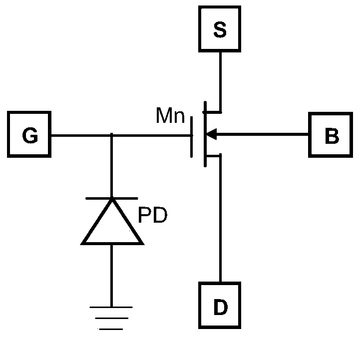
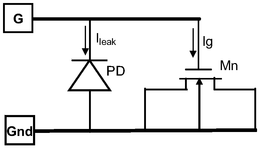
[0009] However, the TDDB test is often carried out at a higher temperature, even higher than 150°C. At this temperature, the leakage current Ileak of the diode is far greater than the leakage current at room temperature, and is even comparable to the gate current Ig Almost, when a constant current is applied to the gate, part leaks through the diode, the lifetime of a large TDDB by the test method is inaccurate
[0010] Therefore, in the prior art, in order to release the current formed in the plasma process, it is necessary to add the protection diode, but because the protection diode has a high leakage current at a relatively high temperature, it will be damaged during the reliability test. The influence of the reliability test structure makes the test results inaccurate, which is an urgent problem to be solved at present

Method used


Image

  • A protection circuit and protection method for a reliability test structure of a semiconductor device
  • A protection circuit and protection method for a reliability test structure of a semiconductor device
  • A protection circuit and protection method for a reliability test structure of a semiconductor device

Examples


Embodiment 1

[0041] A specific embodiment of the present invention will be further described below in conjunction with the accompanying drawings.

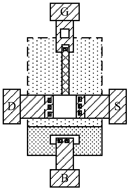
[0042] Among them, the image 3 It is a schematic diagram of the protection circuit of the improved circuit according to the present invention. As shown in the figure, the MOS device in this figure is an NMOS transistor, and the NMOS transistor includes a gate and a source and drain located on both sides of the gate, wherein the protection circuit includes a diode and a fuse structure connected in series, wherein the protection The anode of the diode is connected to one end of the fuse structure, the cathode of the protection diode is connected to the gate of the MOS device to be tested, and the other end of the fuse structure is grounded.

[0043] Preferably, the protection diode is a PN junction, and in the NMOS transistor, the protection diode is a PN junction formed by N-type doping and a P well, wherein 4a-4c are the detection devices des...

Embodiment 2

[0051] A specific embodiment of the present invention will be further described below.

[0052] Wherein, in this embodiment, the MOS device is a PMOS transistor, and the PMOS transistor includes a gate and a source drain located on both sides of the gate, wherein the protection circuit includes a diode and a fuse structure connected in series, wherein the protection diode The anode of the protection diode is connected to one end of the fuse structure, the cathode of the protection diode is connected to the gate of the MOS device to be tested, and the other end of the fuse structure is grounded.

[0053] Preferably, the protection diode is a PN junction. In the PMOS transistor, the protection diode is a PN junction formed by P-type doping and an N well, and its layout structure is the same as that shown in 4a-4c in Embodiment 1. The layout structure schematic diagram of the protection circuit of the detection structure is similar.

[0054] Preferably, the source and drain of t...


PUM


Abstract

The invention relates to a protection circuit and a protection method for a reliability test structure of a semiconductor device. The circuit includes: a MOS device to be tested; a protection diode and a fuse structure arranged in series; wherein the negative electrode of the protection diode is connected to the MOS device to be tested The gate of the protective diode is connected, the anode of the protection diode is connected to one end of the fuse structure, and the other end of the fuse structure is grounded. The protection circuit of the invention can not only eliminate the influence of plasma damage generated in the manufacturing process stage, but also ensure that the influence of the protection circuit on the reliability test is eliminated in the subsequent device test stage. During the manufacturing process of the MOS device, the fuse structure is equivalent to a resistance wire, so that the protection diode plays a role of eliminating plasma damage during the process. When the manufacture is completed and enters the subsequent MOS device testing stage, the fuse structure is disconnected by applying pulse stress, so as to avoid affecting the reliability test results.

Description

technical field [0001] The invention relates to the field of semiconductors, in particular, the invention relates to a protection circuit and a protection method for a semiconductor device reliability testing structure. Background technique [0002] With the continuous development of semiconductor technology, the improvement of integrated circuit performance is mainly achieved by continuously shrinking the size of integrated circuit devices to increase its speed. At present, in order to improve device density, high performance and reduce cost, the size of semiconductor devices is constantly shrinking, which brings great challenges to many aspects such as manufacturing and design. [0003] With the continuous reduction in the size of Ultra Large Scale Integrated circuit (ULSI), the size of the gate dielectric layer in the semiconductor device CMOS is also continuously reduced to obtain higher performance, and the reliability test of semiconductor devices has become a measurem...

Claims


Application Information

Patent Timeline
Patent Type & Authority Patents(China)
IPC IPC(8): H01L23/60H02H9/00
Inventor 朱志炜
Owner SEMICON MFG INT (SHANGHAI) CORP
Learn More