
Panel PET imaging device and method special for local and radiotherapy

The technology of an imaging device and imaging method, which is applied in the fields of radiodiagnostic instruments, treatment, application, etc., can solve the problems of intensified influence of photon non-collinearity, low imaging performance in local areas, and small effective detection solid angle, etc., to achieve The effect of good openness, high adjustability and strong position adjustability

Inactive Publication Date: 2015-08-26
RAYCAN TECH CO LTD SU ZHOU
View PDF11 Cites 17 Cited by
  • Summary
  • Abstract
  • Description
  • Claims
  • Application Information

AI Technical Summary

Problems solved by technology

[0007] 2. The volume is huge. In order to cover the torso of all patients, the traditional PET detector ring is often too large (diameter of at least 50cm or more, generally more than 70cm);
[0008] 3. The cost is expensive, a large detection ring requires a large number of detector modules, and the main cost of PET equipment is the detector;
[0009] 4. The mobility and adjustability are poor, and it must be in the PET imaging room of a special PET imaging center. The patient lies on the hospital bed and moves into the closed detector ring;
[0010] 5. The imaging performance in local areas is low, and the large detector ring leads to a too small effective detection solid angle for the region of interest (Note: The closer the detector is to the imaging object, the larger the coverage solid angle and the higher the detection efficiency, and vice versa. low), large detector rings lead to intensified effects of photon non-collinearity (Note: Photon non-collinearity is an important physical factor affecting the spatial resolution of PET, which is proportional to the diameter of the detector ring: δ=0.0022Dmm, D is the detector diameter)

Method used


Image

  • Panel PET imaging device and method special for local and radiotherapy
  • Panel PET imaging device and method special for local and radiotherapy
  • Panel PET imaging device and method special for local and radiotherapy

Examples


Embodiment Construction

[0048] The invention discloses a partially dedicated flat-panel PET imaging device and method. The partially dedicated flat-panel PET imaging device and method aim at key parts to provide high-performance imaging and have the advantages of openness, adjustability and mobility.

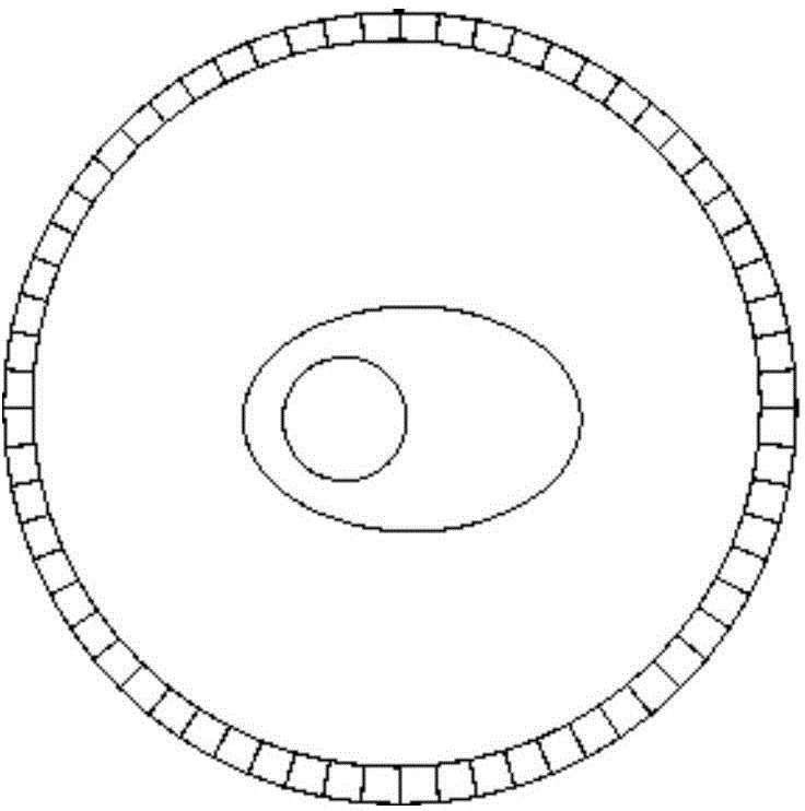
[0049] Such as figure 1 as shown, figure 1 It shows that a PET detector in the prior art has a ring-shaped structure, and the PET detector with this ring-shaped structure has poor openness and cannot perform other clinical operations at the same time.

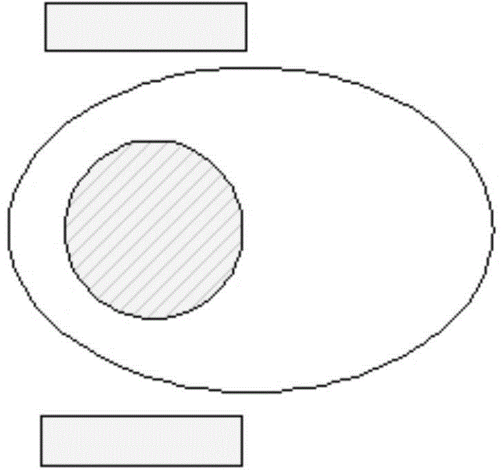
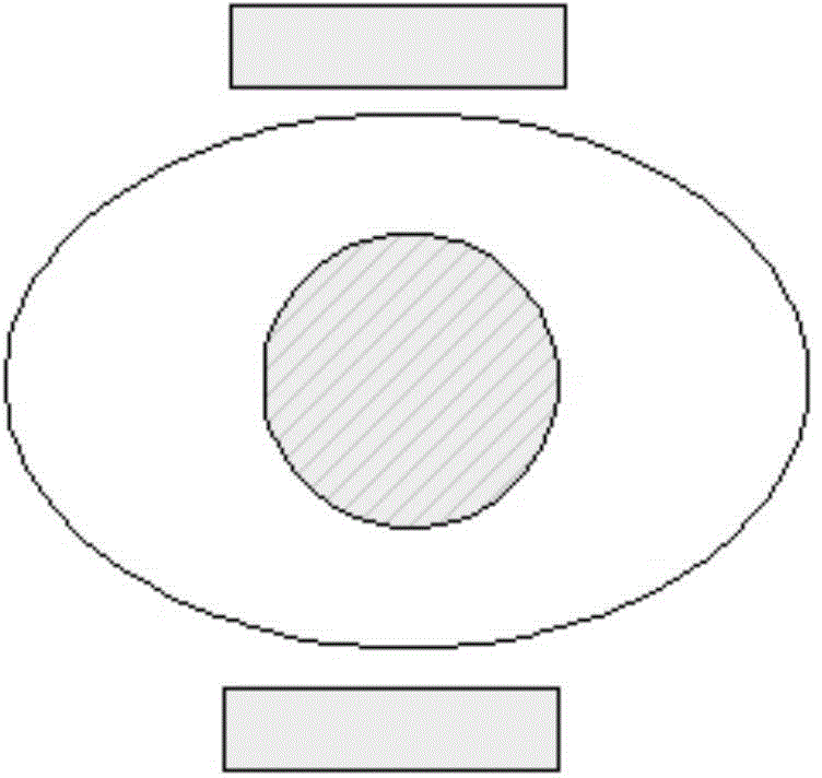
[0050] Such as Figure 2 to Figure 4 As shown, the locally dedicated flat-panel PET imaging device disclosed in the present invention includes at least two groups of flat-panel PET detectors and a mechanical arm system that can support the detectors to move in three directions and support the detectors to rotate at a certain angle. The local dedicated flat-panel PET imaging device of the present invention has good openness, and both sides can be accom...


PUM


Abstract

Disclosed is a topically dedicated flat plate PET imaging device comprising a pair of flat plate PET detectors (200) and a mechanical arm system capable of supporting the detectors (200) to move in three directions, and supporting the detectors (200) to rotate at a certain angle. Also disclosed is a topically dedicated flat plate PET imaging method, comprising: providing a pair of flat plate PET detectors (200) and obtaining the information about regions of interest (400) of an imaging object; determining the imaging field of view of the pair of flat plate PET detectors (200) according to the information about the regions of interest (400), and ensuring that the regions of interest (400) are in the imaging field of view; acquiring corresponding data by means of the pair of flat plate PET detectors (200), performing data correction and calibration, and obtaining a three-dimensional fault activity image through image reconstruction; and completing imaging, and moving the pair of flat plate PET detectors (200) away from the imaging object. The topically dedicated flat plate PET imaging device has a good openness, small size, good mobility, high positional adjustability for the detectors (200), high detection efficiency, and high spatial resolution.

Description

technical field [0001] The invention relates to the field of positron emission tomography imaging, in particular to a locally dedicated flat-panel PET imaging device and method. Background technique [0002] Positron Emission Tomography (PET for short) is a non-invasive imaging method that can non-invasively, quantitatively and dynamically evaluate the metabolic level, biochemical reaction, functional activity and perfusion of various organs of the human body. As a highly sensitive functional imaging device, PET has unique value in early diagnosis, treatment planning, efficacy monitoring and evaluation of tumors, cardiovascular system diseases and nervous system diseases. [0003] With the continuous deepening of the application of PET instruments in clinical diagnosis and treatment, the medical field has put forward new requirements for the performance and functions of PET instruments. The existing clinical PET adopts the traditional closed system architecture, which is fac...

Claims


Application Information

Patent Timeline
IPC IPC(8): A61B6/03A61N5/10
CPCA61B6/037A61B6/4233A61B6/4266A61B6/4411A61N2005/1052A61N5/1049
Inventor 谢庆国万陆肖鹏
Owner RAYCAN TECH CO LTD SU ZHOU
Learn More