Sintering waste heat power generating system based on boosting power circuit

A technology of step-up power supply and waste heat power generation, which is applied in waste heat treatment, energy industry, machine/engine, etc. It can solve the problems of unstable operation of waste heat power generation, low utilization rate of thermal display, high operating cost, etc., so as to improve the scope of application and The effect of using range, reducing equipment investment, reducing equipment investment and operating cost

Inactive Publication Date: 2015-08-26
CHENGDU SINOMETALLURGY ENERGY CONSERVATION ENVIRONMENTAL PROTECTION ENG CO LTD
View PDF4 Cites 0 Cited by
  • Summary
  • Abstract
  • Description
  • Claims
  • Application Information

AI Technical Summary

Problems solved by technology

In view of the defects that the existing sintering waste heat power generation system needs to be equipped with an induction fan to extract the flue gas, the operating cost is high, the failure rate is high, and the waste heat power generation in the waste heat power generation method is unstable and the utilization rate of heat is not high, the purpose of the present invention is to provide A sintering waste heat power generation system and method, without affecting the normal production of the sintering process and ensuring the sintering quality, the sintering waste heat power generation system fully utilizes the flue gas of the non-desulfurization pipe at the tail of the sintering machine and the waste heat of the exhaust gas of the cooler, and adopts sintering There is no induction fan for the flue gas at the tail of the waste heat boiler, and the method of leading out the hot exhaust gas in the first and second stages of the annular cooler and the method of partial recycling can make full use of the flue gas of the sintering machine and the waste heat of the exhaust gas of the annular cooler, reducing equipment investment and reducing Reduce operating costs and increase the power generation of the sintering waste heat power generation system

Method used


Image

  • Sintering waste heat power generating system based on boosting power circuit
  • Sintering waste heat power generating system based on boosting power circuit
  • Sintering waste heat power generating system based on boosting power circuit

Examples


Embodiment

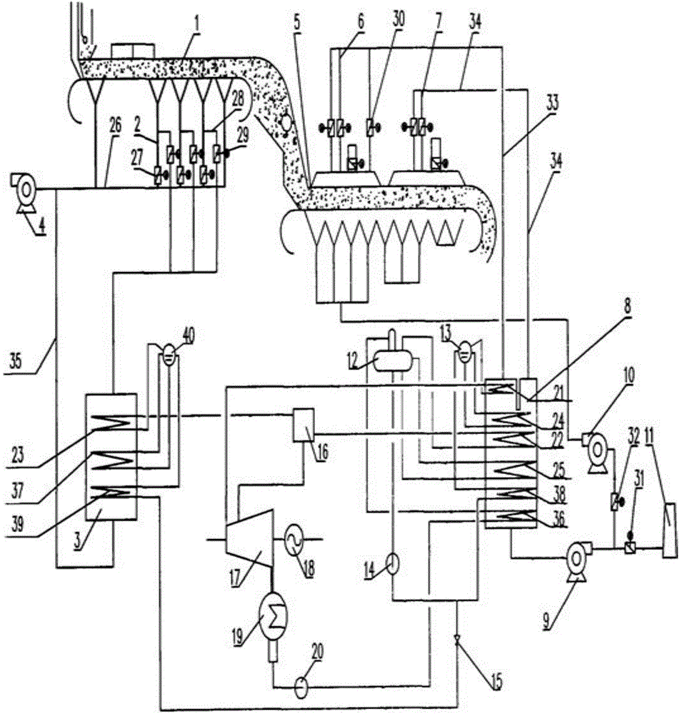
[0025] Such as figure 1 As shown, the present invention includes a sintering machine hot flue gas system, a hot waste gas waste heat utilization system and a sintering waste heat power generation thermal system;

[0026] The hot flue gas system of the sintering machine is as follows: a hot flue gas outlet pipe 2 is provided in each of the bellows at the bottom of the sintering machine 1, and the other end of the hot flue gas outlet pipe 2 communicates with the hot flue gas manifold 26 at the tail. Each hot flue gas outlet pipe 2 is provided with a hot flue gas outlet pipe valve 27 at one end close to the hot flue gas manifold 26 at the tail, and a main exhaust fan 4 is arranged at one end of the hot flue gas manifold 26 at the tail, counting down from the tail of the sintering machine Starting from the second hot flue gas outlet pipe 2, hot flue gas branch pipes 28 and hot flue gas branch pipe valves 29 are arranged on 2 to 4 hot flue gas outlet pipes 2. The other end of the h...


PUM


Abstract

The invention discloses a sintering waste heat power generating system based on a boosting power circuit. The sintering waste heat power generating system comprises a sintering machine hot smoke system, a hot exhaust gas waste heat utilizing system and a sintering waste heat power generating thermodynamic system. The sintering waste heat power generating thermodynamic system is internally provided with a boosting power output system connected to the output end of a steamer power generator. The boosting power output system comprises the boosting power circuit and a storage battery or an electric device connected with the boosting power circuit. The boosting power circuit is composed of a boosting circuit and a power circuit. The stability of the sintering waste heat power generating system is improved, the service life of the sintering waste heat power generating system is prolonged, the internal running circuits of the sintering waste heat power generating system are additionally arranged or changed, and storage battery damage or electric device damage caused by too high fluctuation of voltage is avoided.

Description

technical field [0001] The invention belongs to the technical field of sintering waste heat power generation in iron and steel plants, and in particular relates to a sintering waste heat power generation system based on a step-up power supply circuit. Background technique [0002] In the process of iron and steel production, the energy consumption of the sintering process accounts for about 10% of the total energy consumption, ranking second only to the iron-making process. In the total energy consumption of the sintering process, nearly 50% of the heat energy is discharged into the atmosphere in the form of sensible heat from the flue gas of the sintering machine and the exhaust gas of the cooling machine. Power generation by sintering waste heat is an important measure for steel plants to achieve energy conservation and emission reduction. [0003] The sulfur content of the flue gas in the non-desulfurization flue pipe of the sintering machine is low, and the flue gas temp...

Claims


Application Information

Patent Timeline
Patent Type & Authority Applications(China)
IPC IPC(8): F27D17/00F01K27/00
CPCY02P10/25Y02P80/15
Inventor 不公告发明人
Owner CHENGDU SINOMETALLURGY ENERGY CONSERVATION ENVIRONMENTAL PROTECTION ENG CO LTD
Why Eureka
Try Eureka