Line loss monitoring device

A monitoring device and line loss technology, applied in the direction of measuring device, measuring electricity, measuring electrical variables, etc., can solve the problems of not being able to find and stop in time, too much loss and waste, long line loss period, etc., to achieve good design effect, easy to replace , the effect of low cost

Inactive Publication Date: 2015-08-26
国网山东济南市长清区供电公司 +1
View PDF7 Cites 7 Cited by
  • Summary
  • Abstract
  • Description
  • Claims
  • Application Information

AI Technical Summary

Problems solved by technology

[0006] At present, most of the power supply enterprises use the traditional monthly meter reading method to calculate the line loss statistics. However, this method

Method used


Image

  • Line loss monitoring device
  • Line loss monitoring device
  • Line loss monitoring device

Examples


Embodiment 1

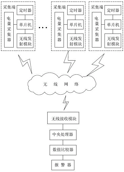
[0024] Such as figure 1 The shown a kind of line loss monitoring device comprises several collecting ends and monitoring ends, and described collecting end comprises single-chip microcomputer, and described single-chip microcomputer drives electric power collector through drive circuit, and described single-chip microcomputer is connected with wireless transmission module and timer respectively connection, the monitoring end includes a wireless receiving module, a central processing unit, a numerical comparator and an alarm, the input of the numerical comparator is connected to the central processing unit, and the output of the numerical comparator is connected to the alarm through a drive circuit , the collection end and the monitoring end perform data communication through a wireless network. Wherein, the single-chip microcomputer is a 51 series single-chip microcomputer, and the wireless network adopts one of the following transmission modes: 3G, 4G, CDMA, GSM, GPRS, WLAN. ...

Embodiment 2

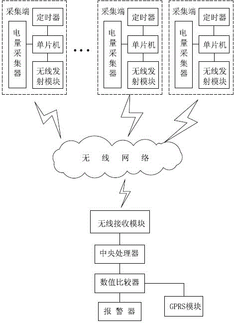
[0038] When the monitoring personnel leave their posts, in order to ensure that the alarm information is conveyed to the monitoring personnel in time, as well as the maintenance personnel patrolling outside, further, such as figure 2 As shown, the monitoring terminal also includes a GPRS module, and the input terminal of the GPRS module is connected to the output terminal of the numerical comparator through the driving circuit. When the numerical comparator draws the conclusion that the current line loss value is greater than the preset value, the When the alarm is started, the GPRS module will also be started. Several phone numbers are preset in the GPRS chip in the GPRS module, and these phone numbers are the working mobile phone numbers of the monitoring personnel and inspection personnel. The GPRS module can send short messages to the inspection and maintenance personnel when starting to inform the alarm information.

Embodiment 3

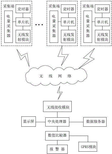
[0040] Since the alarm information is vague, it is impossible to provide better help for the maintenance personnel. In order to know the clear and accurate line loss value, so that the monitoring personnel and the inspection personnel can communicate better, and provide data support for the maintenance work, further, such as image 3 As shown, the monitoring terminal also includes a display screen, which is connected to the central processing unit and can display status values. At the same time, in order to facilitate the accumulation of station area data and provide data support for later power grid upgrades and line design, the monitoring terminal is equipped with a data server, and the data server is connected to the central processing unit for storing line loss data.


PUM


Abstract

The invention provides a line loss monitoring device which comprises a plurality of collecting terminals and a monitoring terminal, wherein each of the collecting terminals comprises a single chip microcomputer which drives an electric quantity collector through a drive circuit and is connected with a wireless transmitting module and a timer; the monitoring terminal comprises a wireless receiving module and a central processing unit; the collecting terminals and the monitoring terminal are in data communication through a wireless network. The line loss monitoring device provided by the invention not only is relatively low in cost and relatively wide in application range, but also can be used for immediately and accurately acquiring the line loss condition and data in a monitoring field so as to accomplish immediate repair and stop problems or behaviors which affect the line loss in an assistant manner. The line loss monitoring device further can be used for accumulating the line loss data in an actual electric power supply process, thereby providing support for normalizing the line loss numerical value.

Description

technical field [0001] The invention relates to the technical field of power control, in particular to a line loss monitoring device. Background technique [0002] Line loss refers to the energy loss dissipated in the form of heat energy, that is, the active power consumed by resistance and conductance. The reasons for the line loss during the transmission of electric energy are as follows: [0003] 1. Resistance effect: the wires of the line, the transformer, and the winding of the motor are all conductors of copper or aluminum materials. When the current passes, it presents a resistance to the current, which is called the resistance of the conductor. In the transmission of electric energy in the power network, the resistance of the conductor must be overcome, resulting in the loss of electric energy, which is seen in the heating of the conductor. Since this loss is caused by the resistance of the conductor, it is called resistive loss, which is proportional ...

Claims


Application Information

Patent Timeline
IPC IPC(8): G01R31/00
Inventor 安涛刁德国国云剑王莹王新肖鹏飞翟乐
Owner 国网山东济南市长清区供电公司
Why Eureka
Try Eureka