
Crossbeam-fixed type high-precision numerical control gantry machining center

A machining center, high-precision technology, applied in the field of machine tools, can solve problems such as affecting the Z-axis motion smoothness, Z-axis motor service life, difficulty meeting processing needs, increasing Z-axis screw wear, etc., to achieve a simple structure and ensure stable the effect of reducing the load

Inactive Publication Date: 2015-09-02
CHONGQING MASITER PRECISION MACHINERY
View PDF8 Cites 1 Cited by
  • Summary
  • Abstract
  • Description
  • Claims
  • Application Information

AI Technical Summary

Problems solved by technology

However, the existing CNC gantry machining centers are bulky, occupy a large area, have poor structural rigidity, and unstable overall precision; at the same time, they vibrate greatly during the working process, resulting in large noise, rapid temperature rise, and low reliability. good
The spindle box of the CNC gantry machining center is arranged vertically, and the weight of the spindle box is basically carried by the Z-axis motor, which will increase the wear of the Z-axis screw rod, affect the stability of the Z-axis movement and the service life of the Z-axis motor
The spindle of the gantry machining center is directly driven by the spindle motor, which can only perform high-speed cutting, and it is difficult to meet different processing needs

Method used


Image

  • Crossbeam-fixed type high-precision numerical control gantry machining center
  • Crossbeam-fixed type high-precision numerical control gantry machining center
  • Crossbeam-fixed type high-precision numerical control gantry machining center

Examples


Embodiment Construction

[0021] Below in conjunction with accompanying drawing and embodiment the present invention will be further described:

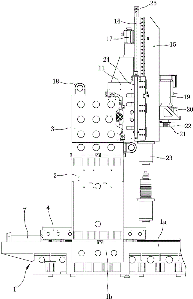
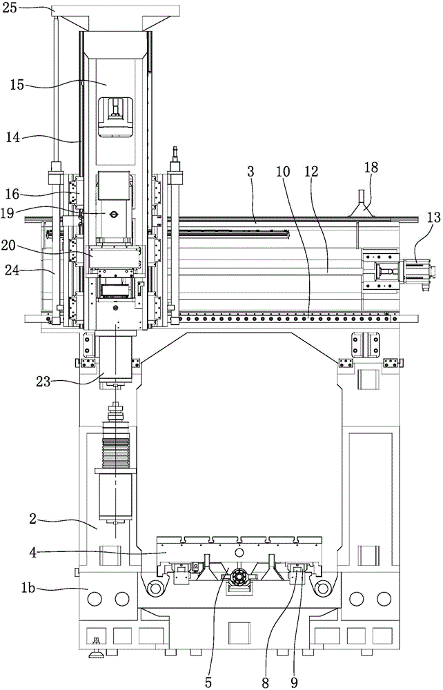
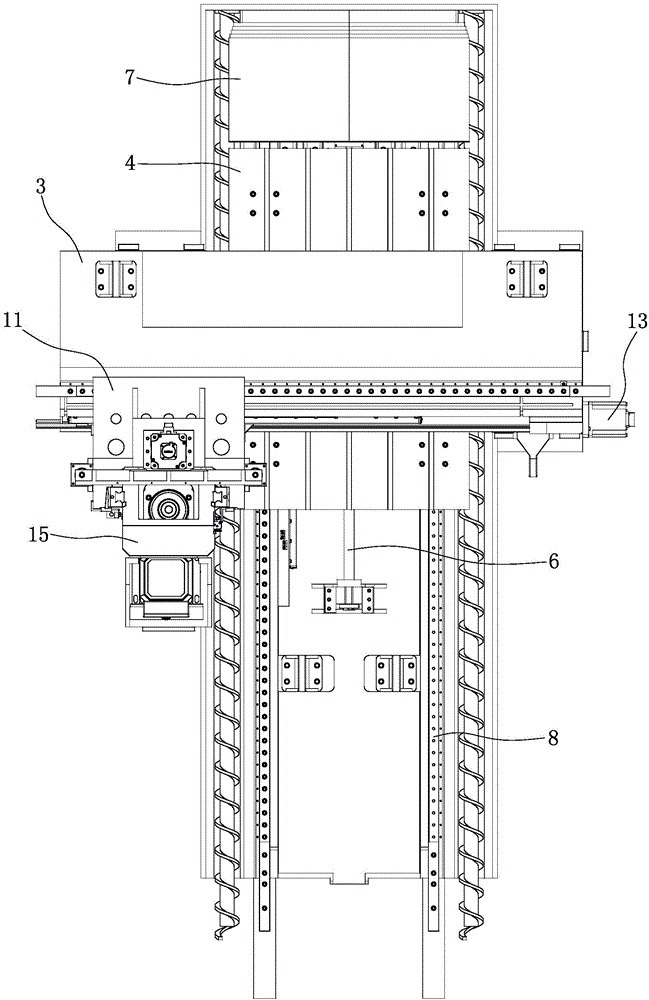
[0022] Such as figure 1 , figure 2 , image 3 As shown, a rectangular support platform 1a is integrally formed on the top of the base 1, supports 1b are symmetrically arranged on the left and right sides of the rear part of the support platform 1a, and columns 2 are fixed on each support 1b, and the tops of the columns 2 on the left and right sides are common. Support beam 3. A workbench 4 is arranged above the support platform 1a, and the workbench 4 is used for positioning the workpiece to be processed. The workbench 4 is located between the two columns 2, and the X-axis nut seat 5 fixed at the bottom of the workbench 4 is threadedly engaged with the X-axis screw rod 6 . The X-axis screw 6 extends in the front-rear direction, and both ends of the X-axis screw 6 are supported on the support table 1 a through bearings and bearing housings. The rear end ...


PUM


Abstract

The invention discloses a crossbeam-fixed type high-precision numerical control gantry machining center which is characterized in that a spindle box (15) is disposed between two Z-axis slide rails (14), and the Z-axis nut seat at the back of the spindle box (15) is matched with a Z-axis screw in a threaded manner; nitrogen balance cylinders (24) are symmetrically disposed on the left and right sides of a Y-axis slide seat (11); the piston rod of each nitrogen balance cylinder (24) extends out upwardly; the output shaft of a spindle motor (19) is connected with the input end of a gear box (20), a drive wheel (21) sleeves the output shaft of the gear box (20), and the drive wheel (21) is connected with a driven wheel on a spindle (23) through a belt (22). The crossbeam-fixed type high-precision numerical control gantry machining center has the advantages that the axial movements are achieved by the large-torque motor and the screw-nut pair, machining of complex profiles can be achieved, high-speed cutting can be achieved, and low-speed and large-torque cutting can be achieved; the gravity of the spindle box is balanced by the nitrogen balance cylinders, and the load of a Z-axis motor can be effectively reduced to guarantee Z-axis movement stability.

Description

technical field [0001] The invention belongs to the technical field of machine tools, and in particular relates to a beam-fixed high-precision numerical control gantry machining center. Background technique [0002] CNC machining center is a high-efficiency automatic machine tool suitable for processing complex parts composed of mechanical equipment and numerical control system. CNC machining centers are currently one of the most productive and widely used CNC machine tools in the world. Its comprehensive processing ability is strong, and the workpiece can complete more processing content after one clamping, and the processing accuracy is high. For batch workpieces with medium processing difficulty, its efficiency is 5 to 10 times that of ordinary equipment, especially it can complete The processing that cannot be completed by ordinary equipment is more suitable for single-piece processing with complex shapes and high precision requirements or small and medium-sized batches...

Claims


Application Information

Patent Timeline
IPC IPC(8): B23Q37/00B23Q11/00
CPCB23Q1/012B23Q37/00B23Q11/00
Inventor 杨勇
Owner CHONGQING MASITER PRECISION MACHINERY
Learn More