A method for suppressing the initiation and propagation of cracks in parts based on laser shock strengthening

A laser shock strengthening and parts technology, applied in the fields of aviation and automobile industry parts, can solve the problems of changing the metallographic structure of the melting area of ​​the parts, the fatigue life of the parts cannot be well guaranteed, and the metallographic structure of the cladding layer is difficult. , to achieve the effect of green repair and life extension technology, improve service life, and prevent the initiation of micro-cracks

Active Publication Date: 2017-06-06
SHENYANG LIGONG UNIV
View PDF9 Cites 0 Cited by
  • Summary
  • Abstract
  • Description
  • Claims
  • Application Information

AI Technical Summary

Problems solved by technology

Substance replenishment, also known as cladding, adds a cladding layer close to the composition of the metal matrix material at the gap crack, but this method requires machining before adding the cladding layer and after the cladding layer, and it is difficult One-time completion is relatively time-consuming, and it is difficult to keep the metallographic structure of the cladding layer consistent with the substrate; external energy supply currently mainly includes heat treatment, application of current pulses, microwave heating and laser heating, etc., that is, to make cracks The melting of the gap makes the crack gradually heal, but this method also changes the metallographic properties of the melting zone of the part due to the introduction of heat, and may even cause a layer of oxide skin on the surface of the part
Therefore, the currently commonly used metal parts repair methods have some shortcomings, and the fatigue life of the parts cannot be well guaranteed. It is necessary to develop a new repair technology that meets the requirements.

Method used


Image

  • A method for suppressing the initiation and propagation of cracks in parts based on laser shock strengthening
  • A method for suppressing the initiation and propagation of cracks in parts based on laser shock strengthening
  • A method for suppressing the initiation and propagation of cracks in parts based on laser shock strengthening

Examples


Embodiment 1

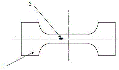
[0031] In this embodiment, the metal part is a 6082 aluminum alloy standard tension-compression fatigue sample with a length of 55 mm and a thickness of 3 mm, with a scratch damage of 0.1 mm in length;

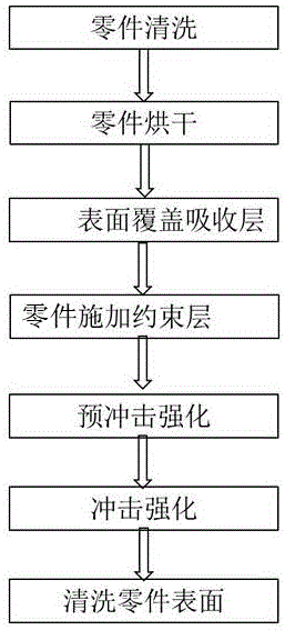
[0032] In this implementation, the crack initiation and propagation of parts are suppressed according to the following steps:

[0033] (1) Clean the aluminum alloy metal parts with damage points with deionized water, then dry them with dry nitrogen, and dry them in a drying oven at 100°C for 10 minutes;

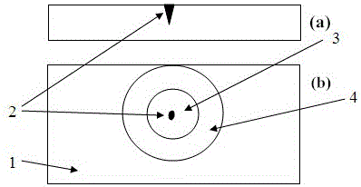
[0034] (2) Surface pretreatment of metal parts. The surface pretreatment of metal parts is to put the metal parts into an ultrasonic cleaning machine equipped with deionized water at a water temperature of 20°C. Blow dry with dry nitrogen, and then put it in a drying oven at 70°C for 20 minutes; in the clean room, cover a layer of black tape with a thickness of 120 μm around the damaged point of the metal part as an absorbing layer;

[0035] (3) Install the metal parts cover...

Embodiment 2

[0039] The metal part of this embodiment is a 6082 aluminum alloy standard tension-compression fatigue sample with a length of 55 mm and a thickness of 3 mm, with a notch damage of 0.05×0.05×0.05 mm in size;

[0040] In this implementation, the crack initiation and propagation of parts are suppressed according to the following steps:

[0041] (1) Clean the aluminum alloy metal parts with damage points with deionized water, then dry them with dry nitrogen, and dry them in a drying oven at 100°C for 10 minutes;

[0042] (2) Perform surface pretreatment on metal parts. The surface pretreatment of metal parts is to put the metal parts into an ultrasonic cleaning machine equipped with deionized water at a water temperature of 24°C. Blow dry with dry nitrogen, and then put it in a drying oven at 70°C for 20 minutes; in the clean room, cover a layer of black tape with a thickness of 100 μm around the damaged point of the metal part as an absorbing layer;

[0043] (3) Install the metal...

Embodiment 3

[0047] The metal part in this embodiment is a 6082 aluminum alloy standard tension-compression fatigue sample with a length of 55 mm and a thickness of 3 mm, and has a pit with a diameter of 0.09 mm and a depth of 1 mm;

[0048] In this implementation, the crack initiation and propagation of parts are suppressed according to the following steps:

[0049] (1) Clean the aluminum alloy metal parts with damage points with deionized water, then dry them with dry nitrogen, and dry them in a drying oven at 100°C for 10 minutes;

[0050] (2) Perform surface pretreatment on metal parts. The surface pretreatment of metal parts is to put the metal parts into an ultrasonic cleaning machine equipped with deionized water at a water temperature of 22°C. Blow dry with dry nitrogen, and then put it in a drying oven at 70°C for 20 minutes; in the clean room, cover a layer of black tape with a thickness of 200 μm around the damaged point of the metal part as an absorbing layer;

[0051] (3) Ins...


PUM

PropertyMeasurementUnit
thicknessaaaaaaaaaa
thicknessaaaaaaaaaa
thicknessaaaaaaaaaa

Abstract

The invention belongs to the technical field of components and parts in aviation and automobile industries, and particularly relates to a method for restraining the initiation and the expansion of a crack of a part based on laser shock peening. According to the method for restraining the initiation and the expansion of the crack of the part based on the laser shock peening, an absorption layer covers the periphery of an impaired loci of a metal part; a restraint layer is applied on the absorption layer; the surface where the impaired loci of the metal part is located is enabled to face a laser beam, is first subjected to laser pre-shock peening processing, and then is subjected to the laser shock peening, and finally the surface of a workpiece is cleaned, so as to obtain a surface-repaired metal part. By using the laser shock peening of the method for restraining the initiation and the expansion of the crack of the part based on the laser shock peening, the expansion of the crack in an impaired area of the part is effectively restrained; the initiation of a microcrack at the impaired loci of the part can be effectively prevented; the service life of the part can be increased by above 30 percent.

Description

technical field [0001] The invention belongs to the technical field of aviation and automobile industry parts, and in particular relates to a method for suppressing the initiation and expansion of cracks in parts based on laser shock strengthening. Background technique [0002] With the development of modern industry, parts are required to work continuously under high temperature, high pressure, high speed, alternating stress load, acid corrosive medium or dust environment, so the surface performance requirements of mechanical product parts are getting higher and higher. By improving the surface properties of materials or repairing worn or partially damaged parts in time, the service life of parts can be effectively extended, which is more and more favored by researchers. [0003] At present, when repairing cracks, scratches or gaps in metal parts, there are mainly two forms according to the healing method: material supply and energy supply. From the cracks of common metal m...

Claims


Application Information

Patent Timeline
Patent Type & Authority Patents(China)
IPC IPC(8): C21D10/00
Inventor 刘军冯艳君宋凯乔红超于洋梅铁民高宏伟石征锦赵延东刘海燕赵亚威杨慧英胡瑞
Owner SHENYANG LIGONG UNIV
Why Eureka
Try Eureka