
Combined intelligent isolation bearing of magnetorheological elastomer

A magnetorheological elastomer, vibration isolation bearing technology, applied in the direction of springs/shock absorbers, springs, shock absorbers, etc., can solve the problems of aggravating magnetic flux leakage, increasing bearing gap, influence, etc., to achieve the use and maintenance. Effects of cost reduction, uniform magnetic field distribution, and size reduction

Active Publication Date: 2015-09-02
DALIAN UNIV OF TECH
View PDF6 Cites 10 Cited by
  • Summary
  • Abstract
  • Description
  • Claims
  • Application Information

AI Technical Summary

Problems solved by technology

The huge coil not only doubles the production, use and maintenance costs of the support, but also brings serious inconvenience to the design of the support layout and construction
In addition, when the huge coil is placed outside, it is necessary to leave a space for the deformation of the support, which must increase the gap between the support and the coil, which intensifies the phenomenon of magnetic flux leakage
Magnetic flux leakage will also affect the surrounding environment, especially nearby electronic equipment
In addition, in order to improve the seismic isolation performance of the structure, it is sometimes necessary to reduce the stiffness and damping of the support. However, the existing magneto-rheological elastomer bearings generally can only increase the stiffness and damping. Realizing reverse adjustment requires a long time to provide a magnetic field. Only using The coil is almost difficult to achieve reverse regulation

Method used


Image

  • Combined intelligent isolation bearing of magnetorheological elastomer
  • Combined intelligent isolation bearing of magnetorheological elastomer
  • Combined intelligent isolation bearing of magnetorheological elastomer

Examples


Embodiment Construction

[0021] The specific embodiments of the present invention will be described in detail below in conjunction with the technical solutions and accompanying drawings.

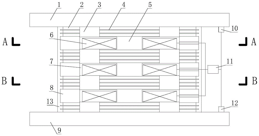
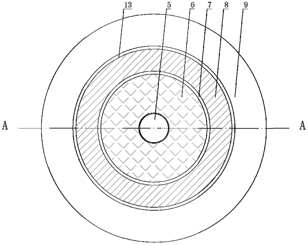
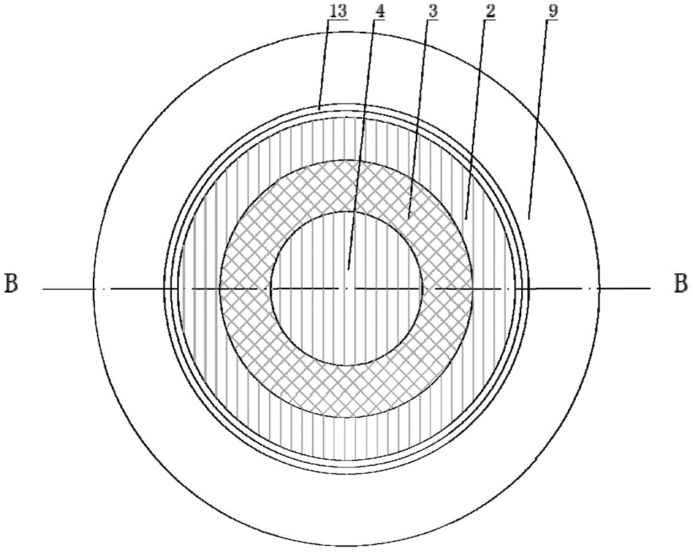
[0022] The specific embodiment of the present invention sees Figure 1 to Figure 3 . from vertical section figure 1 It can be seen that this embodiment is composed of 4 force bearing subassemblies, 3 excitation subassemblies, 2 sensors 10, 12 and 1 controller 11. The two force-bearing subassemblies connected to the upper connecting plate 1 and the lower connecting plate 9 are formed by overlapping and vulcanizing three layers of magnetorheological elastomers and two layers of steel plates, and are vulcanized and stacked on the circular magnetorheological elastomers-steel plates 4 and annular magnetorheological elastomer-steel plate vulcanization lamination 2 are filled with annular lead core 3; the middle two sub-assemblies are composed of four layers of magnetorheological elastomer and three layers of steel plate...


PUM


Abstract

The invention discloses a combined intelligent isolation bearing of magnetorheological elastomer and belongs to the field of structural control. The combined intelligent isolation bearing mainly comprises a stress bearer component, an exciter component, a sensor and a controller; the stress bearer component is composed of a round magnetorheological elastomer-steel plate vulcanized lamination, an annular lead core and an annular magnetorheological elastomer-steel plate vulcanized lamination which are coaxial and which are arranged from inside to outside; the exciter component comprises a core, a coil, an insulation layer and a magnetized steel ring coaxially arranged from inside to outside; a magnetic loop can form in a support; the sensor is mounted on upper and lower connecting plates; the controller adjusts shear stiffness of the support according to signals. The combined intelligent isolation bearing has the advantages that the mechanical and electromagnetic features of materials are made full use, spatial utilization rate and magnetic field utilization rate are high, the magnetic field is uniform with little flux leakage, the size of the coil is greatly reduced, production, usage and maintenance costs are reduced, and the combined intelligent isolation bearing as shaped as a lead-core rubber bearing is convenient to design and construct.

Description

technical field [0001] The invention belongs to the technical field of structural semi-active control, and relates to a combined magnetorheological elastomer intelligent shock-isolation bearing whose stiffness and damping can be adjusted through a magnetic field, using magnetorheological elastomer as a key material. Background technique [0002] Rubber bearing isolation technology is a mature structure passive control technology, and its vibration reduction effect is obvious. In several major earthquakes in recent years, a large number of structures using rubber isolation bearing technology have withstood the test. This passive control technology is simple to implement and highly reliable, but its drawback is that the structure cannot adjust its own stiffness and damping according to different types of seismic wave input during an earthquake. Under the action of long-period earthquakes, the structure may cause resonance, resulting in a catastrophic consequence of the displac...

Claims


Application Information

Patent Timeline
IPC IPC(8): F16F9/53F16F9/32
CPCF16F9/32F16F9/535F16F2224/045
Inventor 欧进萍王奇董旭峰
Owner DALIAN UNIV OF TECH
Learn More