
Boiler flue gas denitration purification system and boiler flue gas denitration purification method

A technology for boiler flue gas and purification system, which is applied in chemical instruments and methods, separation methods, dispersed particle separation, etc. Consumption and other issues to achieve the effect of saving resources, enhancing mixing, and prolonging service life

Active Publication Date: 2015-09-09
NANJING LONGYUAN ENVIRONMENTAL CO LTD
View PDF5 Cites 20 Cited by
  • Summary
  • Abstract
  • Description
  • Claims
  • Application Information

AI Technical Summary

Problems solved by technology

[0003] At present, the main methods used for boiler flue gas denitrification in my country are: flue gas denitrification selective catalytic reduction method (abbreviated as SCR), selective non-catalytic reduction method (abbreviated as SNCR), low-nitrogen combustion, etc., among which SNCR and low-nitrogen combustion denitrification efficiency It is not high enough to achieve deep removal of nitrogen oxides. Although SCR has the advantages of mature and reliable process and high denitrification efficiency, it can stably control nitrogen oxides at 70mg / N m 3 , even close to 60mg / Nm 3
But to reach 50mg / Nm 3 For the following goals, it is necessary to increase the use of catalyst and reducing agent, and the increase of catalyst use will increase the SO at the flue gas outlet. 3 concentration, the increase in reducing agent injection will cause ammonia escape, both of which will lead to air preheater blockage; on the other hand, it will also increase the cost and energy consumption of denitrification,
[0004] Patent CN10773781A discloses a joint denitrification method of SNCR and SCR for coal-fired boilers. A reductant spray gun is arranged on the flue gas channel of the coal-fired boiler, and an SCR reactor loaded with an SCR catalyst is arranged in the tail flue of the boiler. The reductant enters the After the flue gas passes through, SNCR reaction occurs with the flue gas, and then the remaining reducing agent and flue gas pass through the SCR reactor, and the SCR reaction occurs on the surface of the catalyst. However, it is impossible to reduce the nitrogen oxides in the flue gas to 50mg / Nm under the condition that there is no secondary pollution and ammonia escape 3 a bit

Method used


Image

  • Boiler flue gas denitration purification system and boiler flue gas denitration purification method
  • Boiler flue gas denitration purification system and boiler flue gas denitration purification method
  • Boiler flue gas denitration purification system and boiler flue gas denitration purification method

Examples


Embodiment 1

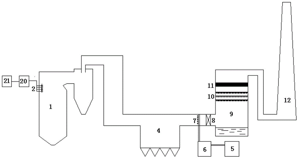
[0039] see figure 1 , a purification system for boiler flue gas denitrification, comprising a circulating fluidized bed boiler 1, a dust collector 4, a desulfurization tower 9 and a chimney 12 connected in sequence, the furnace of the circulating fluidized bed boiler is connected with a denitrification reducing agent injection module, the The deduster 4 is connected to the desulfurization tower 9 through the desulfurization tower inlet flue, and also includes an ozone injection device 7 and a static mixer 9 arranged in the desulfurization tower inlet flue along the flue gas flow direction, and is connected to the ozone injection device 7 The ozone generator 6 and the air separation unit 5 connected with the ozone generator 6.

[0040] In this embodiment, the denitration reducing agent injection module includes a denitration reducing agent storage tank 21, a denitration reducing agent metering device 20 and a denitration reducing agent injection device 2 connected in sequence, ...

Embodiment 2

[0044] Figure 6 It is the second embodiment of the present invention, such as Figure 6 As shown, the difference from Example 1 is that the boiler is a coal-fired boiler 19, an SCR reactor 3 is set between the coal-fired boiler and the dust collector, and a denitration catalyst layer is set in the SCR reactor.


PUM


Abstract

The invention discloses a boiler flue gas denitration purification system which comprises a boiler, a dust collector, a desulfurization tower and a chimney which are connected in sequence, wherein the hearth of the boiler is connected with a denitration reductant jet module, the dust collector is connected with the desulfurization two through an inlet flue of the desulfurization tower; the purification system further comprises an ozone jet device and a static mixer which are arranged in the inlet flue of the desulfurization tower in sequence along the flowing direction of the flue gas, an ozone generator connected with the ozone jet device and an air separation device connected with the ozone generator. The invention further provides a method for performing flue gas denitration by using the system. By ingeniously arranging an ozone denitration device in front of the desulfurization tower of an existing denitration system, not only is the oxynitride concentration of the final flue gas controlled to be not greater than 20mg / Nm<3>, and also no secondary environment pollution is caused; the system is convenient for modification on the basis of an original denitration system; while the resource is saved and the cost is lowered, relatively high denitration efficiency can be guaranteed.

Description

technical field [0001] The invention relates to a purification system and method for boiler flue gas denitrification. Background technique [0002] With the increasingly severe environmental situation, it is expected that 50mg / Nm will be promoted nationwide in the near future 3 NOx emission standards. [0003] At present, the main methods used for boiler flue gas denitrification in my country are: flue gas denitrification selective catalytic reduction method (abbreviated as SCR), selective non-catalytic reduction method (abbreviated as SNCR), low-nitrogen combustion, etc., among which SNCR and low-nitrogen combustion denitrification efficiency It is not high enough to achieve deep removal of nitrogen oxides. Although SCR has the advantages of mature and reliable process and high denitrification efficiency, it can stably control nitrogen oxides at 70mg / N m 3 , even close to 60mg / Nm 3 . But to reach 50mg / Nm 3 For the following goals, it is necessary to increase the use of...

Claims


Application Information

Patent Timeline
Patent Type & Authority Applications(China)
IPC IPC(8): B01D53/75B01D47/06
Inventor 蒋洁周睿丁炜刘轶
Owner NANJING LONGYUAN ENVIRONMENTAL CO LTD
Learn More