High-sensitivity material optical nonlinearity measurement method capable of distinguishing refraction symbols

A high-sensitivity measurement and optical nonlinear technology, which is applied in the field of nonlinear photonics materials and nonlinear optical information processing, can solve the problems of large measurement error, sensitivity limitation, and large error, and achieve the reduction of error, simple optical path requirements, The effect of high measurement sensitivity

Inactive Publication Date: 2015-09-09
SUZHOU MICRONANO LASER PHOTON TECH CO LTD
View PDF5 Cites 5 Cited by
  • Summary
  • Abstract
  • Description
  • Claims
  • Application Information

AI Technical Summary

Problems solved by technology

However, this method is cumbersome when measuring the characteristics of the nonlinear refraction of the sample as a function of time, and the error is relatively large. Put it in two positions to measure the nonlinear refraction time characteristics, and finally remove the influence of nonlinear absorption
(2) The measurement of nonlinear absorption and nonlinear refraction time characteristics cannot be performed at the same time, because the spatial distribution and energy of the laser light at differe...

Method used


Image

  • High-sensitivity material optical nonlinearity measurement method capable of distinguishing refraction symbols
  • High-sensitivity material optical nonlinearity measurement method capable of distinguishing refraction symbols
  • High-sensitivity material optical nonlinearity measurement method capable of distinguishing refraction symbols

Examples


Embodiment 1

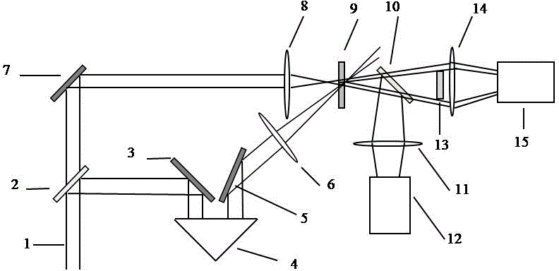
[0026] Embodiment one: see attached figure 2 As shown, a high-sensitivity measurement method for optical nonlinear parameters of materials is based on the detection optical path and the pumping optical path. It can be translated back and forth to change the delay time of the pump light; the detection optical path is mainly composed of a mirror 7, a convex lens 8, a beam splitter 10, a convex lens 11, a circular baffle 13, a convex lens 14, a first detector 12 and a second detector 15 components; the pump light path and the detection light path act on the sample 9 to be tested simultaneously, but the sample 9 is not at the focus of the two lenses.

[0027]A laser pulse 1 is split by means of a beam splitter 2 into a pump beam 3 and a probe beam 8 . The detection beam changes direction through the reflector 7, passes through the convex lens 10 and converges onto the sample 9 placed off-focus, and after passing through the beam splitter 10, it is divided into two beams, and the...


PUM


Abstract

The invention discloses a high-sensitivity material optical nonlinearity measurement pump-probe method. A laser beam is divided into two beams, and a sample is located a certain distance behind the focus of a lens, so that the change of far-field spots is maximized. Pumping light acts on the sample to be detected through time delay, so that the nonlinear sample conducts nonlinear absorption and nonlinear refraction; emergent probe light is divided into two beams by a spectroscope, one beam enters a first probe, and the other passes through a circular baffle of which the center is superposed with the optical axis and then enters a second probe. The method is characterized in that in the path of the probe light, the circular baffle of which the center is superposed with the optical axis is placed on the far field, and the sample is located a certain distance behind the focus of the lens, so that the change of far-field spots is maximized. The following measurement steps are included: firstly, placing the sample to be detected, using the two probes to respectively collect the energies of probe light at different times; secondly, processing probe light energy curves at different delay times to obtain optical nonlinearity parameters. A measurement system working according to the method is extremely high in sensitivity and simple in data processing, realizes simultaneous but not separated measurement of nonlinear absorption and nonlinear refraction, can distinguish nonlinear refraction symbols and is accurate in measurement result.

Description

technical field [0001] The invention relates to a method for testing or analyzing materials by using optical means, in particular to a method for studying the nonlinear optical physical mechanism of materials and measuring its optical physical parameters, belonging to nonlinear photonics materials and nonlinear optical information processing field. Background technique [0002] The rapid development of the field of nonlinear optics is inseparable from the research on optical nonlinear materials. Finding ideal optical nonlinear materials for various applications is a very important task in the field of nonlinear optics. Materials with large optical nonlinear coefficient and ultrafast photoresponse are considered as emerging materials for manufacturing high-speed optoelectronic devices, and have great potential application value in the field of optical engineering, such as all-optical switches and other components. The study of optical nonlinear materials requires the help o...

Claims


Application Information

Patent Timeline
IPC IPC(8): G01N21/31G01N21/41
Inventor 宋瑛林杨俊义
Owner SUZHOU MICRONANO LASER PHOTON TECH CO LTD
Why Eureka
Try Eureka