Method for three-dimensional representation of stratified structure micrometer CT imaging of turbine blade heat barrier coating

A technology of thermal barrier coating and layered structure, applied in the direction of material analysis using radiation, can solve the problems of interference with 3D segmentation accuracy, low signal-to-noise ratio of reconstructed images, and unsatisfactory reconstruction effect of micro-CT systems, etc., to achieve The effect of improving the quality of reconstructed images and improving the signal-to-noise ratio

Inactive Publication Date: 2015-09-09
NANCHANG HANGKONG UNIVERSITY
View PDF6 Cites 26 Cited by
  • Summary
  • Abstract
  • Description
  • Claims
  • Application Information

AI Technical Summary

Problems solved by technology

In 2005, Ramesh mentioned in the patent application (7298818) the idea of ​​constructing a CT imaging system to detect the microstructure inside the thermal barrier coating, but the reconstruction effect of the conventional micro-CT system is not ideal
[0005] Although the three-dimensional structural information of thermal barrier coatings can be obtained by micro-CT at present, the signal-to-noise ratio of the reconstructed image is not high, and the reconstructed image is seriously affected by beam hardening artifacts, which seriously interfere with the three-dimensional segmentation accuracy, and the bonding layer and Insufficient contrast between the base alloys makes it difficult to separate the bond coat from the base alloy

Method used


Image

  • Method for three-dimensional representation of stratified structure micrometer CT imaging of turbine blade heat barrier coating
  • Method for three-dimensional representation of stratified structure micrometer CT imaging of turbine blade heat barrier coating
  • Method for three-dimensional representation of stratified structure micrometer CT imaging of turbine blade heat barrier coating

Examples


Embodiment Construction

[0023] The present invention will be described in detail below with reference to the drawings, including the following steps:

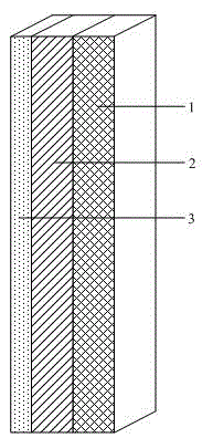
[0024] (1) First use molybdenum wire cutting equipment to cut a 0.5mm (width) × 0.5mm (height) × 10mm (length) sample along the middle part of the thermal barrier coating, and then use a universal glue to glue the sample on a regular support. Grind with metallographic sandpaper to 0.3mm×0.3mm×10mm, soak in acetone solution to remove the universal glue, and then use focused ion beam (FIB) to uniformly process the thickness (height direction) of the thermal barrier coating sample to 0.25mm, and retain the base alloy The thickness is about 50μm, such as figure 1 As shown, the thickness of the ceramic heat insulation layer 1 is 100μm, the thickness of the bonding layer 2 is 100μm, and the thickness of the base alloy 3 is 50μm. By reducing the thickness of the base alloy to improve the X-ray transmittance in micron CT scanning, the ultrasonic cleaning equipmen...


PUM

PropertyMeasurementUnit
densityaaaaaaaaaa
thicknessaaaaaaaaaa

Abstract

The invention discloses a method for three-dimensional representation of stratified structure micrometer CT imaging of a turbine blade heat barrier coating. The method comprises the following steps: preparing a double-layer-structure heat barrier coating micrometer CT scanning sample; firstly, carrying out micrometer CT scanning on the heat barrier coating sample, carrying out ring artifact and beam hardening correction on projection data, then carrying out three-dimensional reconstruction to obtain three-dimensional stratified structure information, establishing a three-dimensional structure analysis model, and carrying out characteristic segmentation and extraction on three components, namely a ceramic heat insulating layer, a bonding layer and matrix alloy; then, analyzing the thickness of the coating, extracting the distribution of holes in the coating, calculating the porosity, extracting the interface topography of the coating, and analyzing structure characteristics such as internal defects; and finally, estimating the preparation process quality of the heat barrier coating by integrating the composition, thickness, porosity distribution, interface topography and the like. The method for three-dimensional representation of the stratified structure of the heat barrier coating provided by the invention is suitable for estimation and optimization of the spraying process quality of the heat barrier coating, so that the quality of the heat barrier coating can be well controlled.

Description

Technical field [0001] The invention belongs to a three-dimensional characterization method of coating structure in the non-destructive detection range of a thermal barrier coating of a turbine blade, and specifically is a three-dimensional characterization method of a micron CT imaging of a layered structure of a thermal barrier coating of a turbine blade. Background technique [0002] The working conditions of aero-engine turbine blades are very harsh. They are not only scoured by high temperature, high pressure, and high-speed airflow, but also subjected to huge centrifugal force, aerodynamic force, thermal stress, alternating force and random load. As the combustion temperature, thrust-to-weight ratio and thermal efficiency of the engine increase, the working conditions of the engine turbine blades, especially the gas temperature in the combustion chamber, have reached 1700℃-1800℃, causing the service temperature of the turbine blades to reach or exceed that of superalloy and ...

Claims


Application Information

Patent Timeline
Patent Type & Authority Applications(China)
IPC IPC(8): G01N23/04
Inventor 敖波邬冠华吴伟邓翠贞
Owner NANCHANG HANGKONG UNIVERSITY
Why Eureka
Try Eureka