Small electromagnetic acceleration system

An acceleration system, electromagnetic technology, applied in control systems, electrical components, AC motor control and other directions, can solve the problems of low energy conversion efficiency, low acceleration efficiency, large quality of energy storage devices, etc., to achieve high energy conversion efficiency, reduce switching Loss, the effect of improving acceleration efficiency

Inactive Publication Date: 2015-09-09
YUNNAN NORMAL UNIV
View PDF3 Cites 4 Cited by
  • Summary
  • Abstract
  • Description
  • Claims
  • Application Information

AI Technical Summary

Problems solved by technology

[0007] 1. Traditional accelerators usually adopt a single-stage acceleration mode. The surge is extremely high, and ordinary switches cannot bear it, but the price of high-power switches is extremely expensive. Moreover, even an arc-extinguishing switch will be damaged due to contact when high-voltage and high-current are connected. Resistance and ablation, resulting in short life of the switch, and the loss is also very large, making the acceleration efficiency low
[0008] 2. The traditional step-up method is low-frequency (most of them use "220V, 50HZ" to rise to high voltage through a transformer), which is bulky, heavy, small in power, and low in energy conversion efficiency.
[0009] 3. The accelerators currently in use are generally industrial and military. Although the accelerated object carries a large kinetic energy, the mass of the energy storage device is also very large. Generally, several warehouses are used to store the electric energy used for one launch.
Such a device is bulky and cumbersome, cannot be transported, and its internal structure is closed, so it cannot directly demonstrate the acceleration principle and working mechanism for people
Moreover, some modern experiments are limited by the development of computer technology, and it is impossible to calculate and analyze the nonlinear problems caused by the introduction of ferromagnetic substances in electromagnetic accelerators. Therefore, a large number of experiments are required to find a set of parameters with slightly higher efficiency (because the system There are 11 independent variables that affect the acceleration efficiency and speed), and the efficiency is generally low
[0010] 4. Traditional electromagnetic accelerators can only work in a single mode (magnetic resistance mode or induction mode)

Method used


Image

  • Small electromagnetic acceleration system
  • Small electromagnetic acceleration system
  • Small electromagnetic acceleration system

Examples


Embodiment Construction

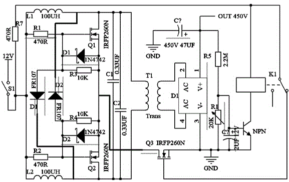
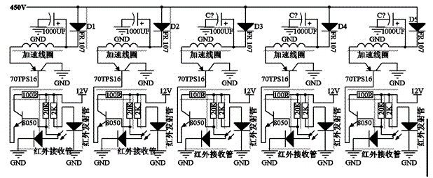
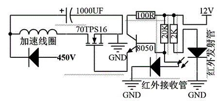
[0035] like Figure 1-4 as shown, figure 1 A structural block diagram of a small electromagnetic acceleration system proposed by the present invention; figure 2 It is a ZVS inverter and voltage automatic control circuit diagram of a small electromagnetic acceleration system proposed by the present invention; image 3 It is a circuit connection diagram of a small electromagnetic acceleration system proposed by the present invention; Figure 4 A circuit diagram of accelerated ferromagnetic materials for a small electromagnetic acceleration system proposed by the present invention.

[0036] refer to Figure 1-4 , a small electromagnetic acceleration system proposed by an embodiment of the present invention, comprising:

[0037] The ZVS boost module converts the input low-voltage DC 12V-24V into high-frequency AC through a double-inductor ZVS circuit, and then inputs a high-frequency transformer to boost the voltage. The peak value is higher than 450V, and then performs full-...


PUM


Abstract

The present invention provides a small electromagnetic acceleration system which comprises a ZVS boost module which converts low voltage direct current into high frequency alternating current, a power supply module which provides low voltage direct current to the ZVS boost module, a voltage control module which carries out automatic controlling on the output voltage of the ZVS boost module, a control signal module which is used for detecting the position of an accelerated object and generating a control signal, a coaxial coil set module for generating a strong pulse magnetic field to accelerate a magnetic or non-magnetic conductor, a switch tube module which is formed by a solid-state switch, controlled by the signal of the control signal module and used for conducting a capacitor and an emitting coil circuit, a motherboard with the integration of interfaces which are connected to the above modules and each acceleration unit capacitance and voltage indication, and a speed measurement module which is used for detecting the speed of the accelerated object. The system has the advantages of small size, light weight, high efficiency, long life, and the direct display of an acceleration process to people.

Description

technical field [0001] The invention relates to the technical field of electromagnetic accelerators, in particular to a small electromagnetic accelerator system. Background technique [0002] Currently commonly used electromagnetic accelerators include reluctance coil accelerators and synchronous induction coil accelerators; [0003] Reluctance coil accelerator: It consists of a series of solenoid driven coils and a yoke core of ferromagnetic material. The so-called reluctance refers to the resistance that prevents the magnetic circuit around the coil from establishing magnetic flux. Obviously, placing ferromagnetic material in the coil lumen can reduce the reluctance. As the core moves, the reluctance of the magnetic circuit around the coil changes, thus exerting a force on the core projectile. The iron core of ferromagnetic material has a greater magnetic permeability (μ p >>1). When the iron core travels to the center of the coil, the magnetic flux is easier to...

Claims


Application Information

Patent Timeline
Patent Type & Authority Applications(China)
IPC IPC(8): H02P25/06
Inventor 段剑金王学浩方达周海春郭杰温元斌许林冯小波
Owner YUNNAN NORMAL UNIV
Why Eureka
Try Eureka