Urea hydrolysis ammonia-production equipment and method

A technology of urea hydrolysis and equipment, which is applied in the field of denitrification raw material gas preparation equipment and preparation, to achieve the effect of easy transformation and timely flow response

Inactive Publication Date: 2015-09-16
CHENGDU RAISE ENVIRONMENTAL PROTECTION TECH CO LTD
View PDF4 Cites 0 Cited by
  • Summary
  • Abstract
  • Description
  • Claims
  • Application Information

AI Technical Summary

Problems solved by technology

[0005] To further optimize the structure of urea decomposition equipment in view of the above, to provide a new type of ammonia production equipment that can respond well to the consumption of denitrification ammonia gas, and the urea decomposition

Method used


Image

  • Urea hydrolysis ammonia-production equipment and method
  • Urea hydrolysis ammonia-production equipment and method
  • Urea hydrolysis ammonia-production equipment and method

Examples


Embodiment 1

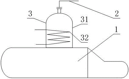
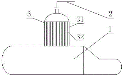
[0027] Such as Figure 1 to Figure 4 As shown, a kind of urea hydrolysis ammonia production equipment comprises ammonia reactor body 1 and gas outlet pipeline 2 connected on the gas outlet of ammonia reactor body 1, there is also a series connection between the ammonia reactor body and outlet pipeline 2 The anti-coagulation buffer 3, the anti-coagulation buffer 3 includes a container body 31 provided with an air inlet and an air outlet, and a heating device 32 arranged on the container body 31, the air inlet and the ammonia reactor body 1 The air outlet of the air outlet is connected, and the inlet end of the air outlet pipeline 2 is connected to the air outlet of the container body 31 .

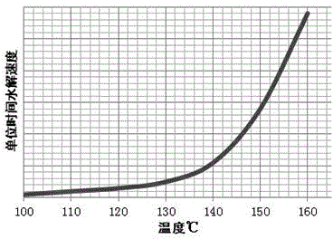
[0028] According to its reaction kinetics, the hydrolysis of urea to ammonia belongs to the first-order reaction, such as image 3 As shown, the reaction kinetic parameters are mainly a function of temperature. Conventional urea hydrolysis reactors are all designed with constant pressure a...

Embodiment 2

[0031] Such as figure 1 , figure 2 and Figure 4 , this embodiment is further limited on the basis of embodiment 1: as figure 1 , as a form of heating equipment 32 with relatively uniform temperature distribution on the heating surface and low operating cost of the heat source, the heating equipment 32 is a heat exchange coil arranged inside the container body 31 . Based on the internal pressure or exhaust pressure of the existing ammonia reactor body 1, combined with the actual temperature at which the components in the ammonia-containing product gas recondense to form solids or crystals under this pressure condition, the thermal fluid of the heat exchange coil should be steam . As the implementation of this solution in this embodiment, due to the structure of anti-coagulation buffer 3, the internal pressure of ammonia reactor body 1 may rise in some cases, such as the gas output of ammonia-containing products is greater than that of denitrification When the system is co...

Embodiment 3

[0036] This embodiment provides a method for using the above equipment to realize ammonia production by urea hydrolysis. This method is similar to the structural design of any one of the above-mentioned embodiments, and can achieve the same technical effect. The above-mentioned structure is based on this method. Urea is hydrolyzed to produce ammonia. The method is to heat urea aqueous solution to obtain ammonia-containing product gas containing ammonia components, and temporarily store and heat the ammonia-containing product gas in the subsequent transmission process of ammonia-containing product gas.


PUM


Abstract

The invention discloses urea hydrolysis ammonia-production equipment and a method. The method and equipment have similar design ideas and can produce the same technical effects. The urea hydrolysis ammonia-production equipment is characterized in that a special anticoagulation buffer is arranged between an ammonia-production reactor main body and an outlet pipe, the container main body of the anticoagulation buffer can be used as a buffer storage space for storing gas discharged by the ammonia-production reactor main body, and a heating device is used for heating the discharged gas. The urea hydrolysis ammonia-production equipment can timely satisfy denitration system requirements on ammonia-containing product gas, can provide stable and timely flow response ammonia-containing product gas for a denitration system, and can prevent solids or crystals produced by reflux condensation of gas ingredients in the ammonia-containing product gas thereby preventing solid or crystal-caused shrinking and even blocking of flowing gaps of pipes, pipe members and instruments and low ammonia-production reactor main body ammonia-production efficiency caused by the shrinking and even blocking of flowing gaps. The buffer storage space and the heating equipment form an integral structure so that urea hydrolysis ammonia-production equipment reconstruction is convenient.

Description

technical field [0001] The invention relates to the field of denitrification raw material gas preparation equipment and a preparation method, in particular to a urea hydrolysis ammonia production equipment and method. Background technique [0002] In my country, industries such as metallurgy, petrochemicals, fertilizers, and urban coal gasification have a large amount of industrial gas emissions. With the gradual emphasis on environmental issues, my country officially implemented the "Emission Standards of Air Pollutants for Thermal Power Plants" in 2012, adjusting the The emission concentration limit of air pollutants puts forward stricter requirements for enterprises that implement emissions. An important exhaust gas in industrial gases is flue gas nitrogen oxides. At present, in all measures to control flue gas nitrogen oxide emissions, selective catalytic reduction (SCR method) flue gas removal of nitrogen oxides is the most important. One of the purification technology ...

Claims


Application Information

Patent Timeline
IPC IPC(8): C01C1/08
Inventor 赵梦源赵青刘小云高良海张玲刘洋罗然郑伟
Owner CHENGDU RAISE ENVIRONMENTAL PROTECTION TECH CO LTD
Why Eureka
Try Eureka