
Combined fireproof cable tray for power supply system cable and installation method of combined fireproof cable tray

A technology of a power supply system and an installation method, which is applied to electrical components and other directions, can solve the problems of increasing the unexpected frequency of the power supply system, troublesome secondary installation of bridges, poor fire resistance and fire resistance, etc., so as to save materials and resources, shorten working time, and prolong use. effect of life

Active Publication Date: 2015-09-16
JIANGSU WEITONG ELECTRICAL EQUIP
View PDF4 Cites 20 Cited by
  • Summary
  • Abstract
  • Description
  • Claims
  • Application Information

AI Technical Summary

Problems solved by technology

[0002] At present, frequency conversion power supply and shore power supply are often used in the power supply system. During operation, the laying of cables for power transmission has become a major problem. The laying is irregular, which will affect future disassembly and maintenance, and will also increase accidents in the power supply system. frequency; the cable tray product is a new type of cable laying device developed by industrially developed countries in the early 1960s; with the high development of electrification and automation, especially the change of power distribution mode, the direct burial of trenches and the laying of cables on brackets are no longer enough. The use requirements are replaced by a cable bridge with low cost, fast construction, flexible wiring, easy loading and unloading, not limited by location, and beautiful at the same time, thus speeding up the construction progress, ensuring quality, and realizing product standardization, Serialization and generalization; bridges are widely used in petroleum, chemical, telecommunications and other industries. Most of the existing bridges are integrally fixed. During transportation, the transportation of integral bridges is very inconvenient; on the other hand, When the bridge frame is changed and expanded, its installation environment often changes. Since the bridge frame is fixed, it will bring trouble to the secondary installation of the bridge frame.
[0003] The existing bridges are prone to aging and corrosion due to long-term exposure during use, and the fire resistance and fire resistance are poor in the event of a fire, which affects the service life and increases the cost; in addition, due to the large size of the bridge during installation, the installation operation is inconvenient and takes a long time , and the amount of labor is also large, therefore, developing a bridge frame that can overcome the above defects has become a technical problem to be solved urgently by those skilled in the art

Method used


Image

  • Combined fireproof cable tray for power supply system cable and installation method of combined fireproof cable tray

Examples


Embodiment 1

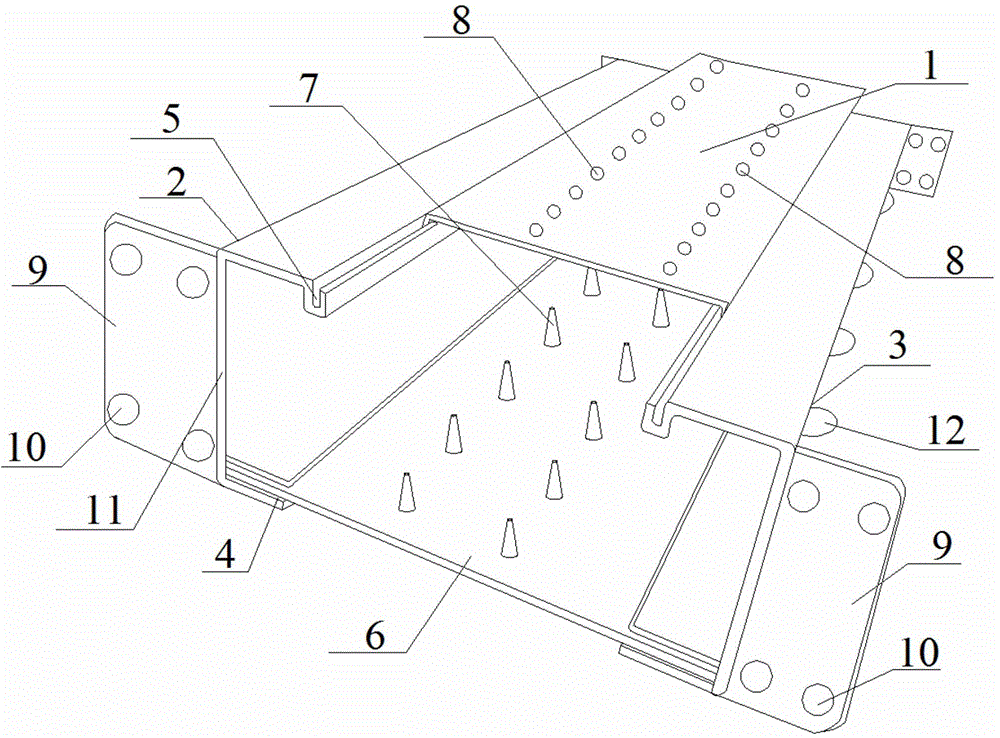
[0034] This embodiment provides a combined fireproof bridge for power supply system cables, the structure of which is as follows: figure 1 As shown, it includes the trough frame and the protective cover 1 arranged on the trough frame. The trough frame is coated with a fire-proof and heat-insulating layer. The fire-proof and heat-insulating layer is a fiber composite heat-insulating board. Connected to the channel frame, the channel frame is composed of the left side wall beam 2, the right side wall beam 3 and the bottom plate 6 arranged between the left and right side wall beams, wherein:

[0035] The shield 1 includes a shield plate and buckles extending from both ends of the shield plate, the buckles are perpendicular to the shield plate, two rows of round holes 8 are arranged along the length direction of the shield plate, and each row has at least 10 round holes 8 ;

[0036] The left side wall beam 2 has the same structure as the right side wall beam 3. The left side wall...

Embodiment 2

[0039] This embodiment provides an installation method for a combined fireproof bridge for power supply system cables in the above-mentioned embodiment 1. The installation method specifically includes the following steps:

[0040] (1) Preparation for installation: Carry out technical clarification according to the approved construction plan, calculate the actual demand for the bridge frame according to the construction plan, check and accept the bridge frame and its accessories on site, and the specifications and quantities should meet the requirements of the construction plan;

[0041](2) Bridge positioning and marking: According to the construction drawing and design plan, find out the relative elevation of the horizontal, vertical, turning and the ground and the relative distance between the wall along the direction of the bridge, pop up the corresponding lines or lines, and draw them evenly and equidistantly The position of the column, the bending radius of the bridge turni...


PUM


Abstract

The invention discloses a combined fireproof cable tray for a power supply system cable. The combined fireproof cable tray includes a channel and a protective cover; the channel is composed of a left side wall beam and a right side wall beam which are in bilateral symmetry, and a bottom plate; the protective cover includes a protective cover plate and clamping buckles; two rows of round holes are uniformly formed in the protective cover plate; the left side wall beam has the same structure as the right side wall beam; the left side wall beam is composed of a side wall plate and a fixing groove; the upper end of the side wall plate extends outwards so as to form a slide groove; the protective cover slides on the left side wall beam and the right side wall beam through the clamping buckles; fixing frames symmetrically extend out from two ends of the side wall plate; fixing holes are formed in the fixing frames respectively; two rows of vent pipes are uniformly formed in the bottom plate; and the bottom plate is inserted into the fixing grooves of the left side wall beam and the right side wall beam, so that a U-shaped structure of the channel can be formed. The invention also provides an installation method of the combined fireproof cable tray. The installation method of the combined fireproof cable tray has the advantages of being simple and feasible, short installation time, low labor intensity and high work efficiency. The combined fireproof cable tray has the advantages of simple structure, convenience in transportation, simple assembly and disassembly and good fireproof performance, and can protect the cable.

Description

technical field [0001] The invention relates to a cable laying device in a power supply system, in particular to a combined fireproof bridge frame for cables in a power supply system and an installation method thereof. Background technique [0002] At present, frequency conversion power supply and shore power supply are often used in the power supply system. During operation, the laying of cables for power transmission has become a major problem. The laying is irregular, which will affect future disassembly and maintenance, and will also increase accidents in the power supply system. frequency; the cable tray product is a new type of cable laying device developed by industrially developed countries in the early 1960s; with the high development of electrification and automation, especially the change of power distribution mode, the direct burial of trenches and the laying of cables on brackets are no longer enough. The use requirements are replaced by a cable bridge with low ...

Claims


Application Information

Patent Timeline
IPC IPC(8): H02G3/04H02G3/06
Inventor 倪道宏王跃林朱凯
Owner JIANGSU WEITONG ELECTRICAL EQUIP
Features
  • Generate Ideas
  • Intellectual Property
  • Life Sciences
  • Materials
  • Tech Scout
  • Unparalleled Data Quality
  • Higher Quality Content
  • 60% Fewer Hallucinations
Learn More