High-precision clock distribution and phase automatic compensation system and phase adjusting method thereof

A high-precision clock and automatic compensation technology, applied in time division multiplexing systems, electrical components, multiplexing communications, etc., can solve the problems of failure to take measures to reduce phase modulation errors, sensitivity to temperature changes of receivers and cables, and GPS The receiving system is expensive and other problems, to achieve the effect of increasing stability and reliability, simple structure, and high phase modulation accuracy

Active Publication Date: 2015-09-16
UNIV OF SCI & TECH OF CHINA
View PDF6 Cites 20 Cited by
  • Summary
  • Abstract
  • Description
  • Claims
  • Application Information

AI Technical Summary

Problems solved by technology

A traditional clock distribution method for physical experiments is to use clock links to distribute clocks. For example, the clock system of the Beijing Spectrograph (BESIII) Time-of-Flight Detector (TOF) introduces the RF signal of the accelerator into the VME chassis through an 80m phase-stable optical fiber. The disadvantage of the method is that the clock link is expensive and expensive, and it is often designed according to different environments and needs, and the versatility is not strong
[0004] Another commonly used clock synchronization method is to use GPS for clock distribution. Auger experimented with GPS receivers for frequency and time synchronization, and calibrated the fixed deviation of GPS receivers in the laboratory in advance. At 3000km 2 GPS receivers are installed on 1,600 water Cherenkov detectors, and the time synchronization precision is better than 20ns. The disadvantage of this method is that the GPS receivi

Method used


Image

  • High-precision clock distribution and phase automatic compensation system and phase adjusting method thereof
  • High-precision clock distribution and phase automatic compensation system and phase adjusting method thereof
  • High-precision clock distribution and phase automatic compensation system and phase adjusting method thereof

Examples


Embodiment Construction

[0051] In order to make the object, technical solution and advantages of the present invention clearer, the present invention will be described in further detail below in conjunction with specific embodiments and with reference to the accompanying drawings.

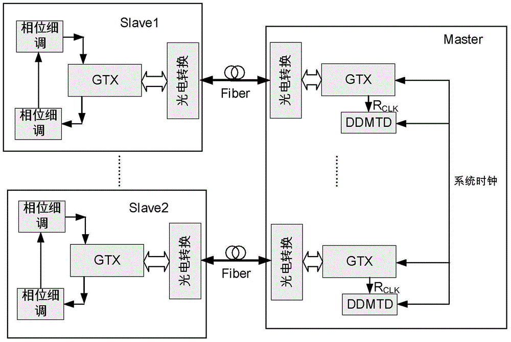
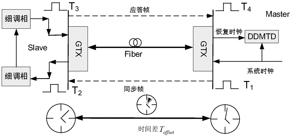
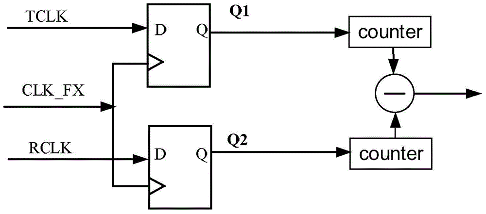
[0052] The principle of the present invention is: based on the traditional precise clock synchronization protocol (PTP), the clock distribution module (Master) sends a synchronization frame to the front-end electronics node (Slave), and the Slave sends a response frame to the Master after receiving the synchronization frame. Master and Slave measure send and receive time and calculate round-trip time from the measurements. In the PTP protocol, the measurement and adjustment of time are all performed by counters, and the precision is limited. In order to improve the precision, the present invention adopts DDMTD to cooperate with the counter to measure time, and adopts FPGA PLL to cooperate with the counter to perform time ...


PUM


Abstract

The invention discloses a high-precision clock distribution and phase automatic compensation system and a phase adjusting method thereof. The system comprises a clock distribution module (master) and a plurality of front-end electronics nodes (slave). The master distributes clocks to the multiple slaves by using fibers. The master sends the clocks to the slaves by the fibers; after receiving the clocks, the slaves return the clocks to the master again; the master carries out dynamic measurement on the sum of round-trip time of the clocks to obtain uplink and downlink delay time of the clocks and sends measurement results to the slaves; and according to the measurement results, the slaves carries out dynamic phase adjustment on the received clocks, so that phase synchronization of the slaves and the master can be maintained. With the system and method, the phase synchronization precision is improved and a phase adjustment error caused by the temperature change can be reduced.

Description

technical field [0001] The present invention relates to the technical field of high-precision clock distribution synchronization, in particular to a field-programmable-gate-array (FPGA)-based multi-node high-precision clock distribution and phase in a large-scale space (~1km) Automatic compensation system and its phase adjustment method. Background technique [0002] Clock phase synchronization technology was initially widely used in the field of network communication, such as remote billing, whose synchronization accuracy can reach the order of hundreds of milliseconds; IP network packet delay monitoring, whose synchronization accuracy is better than 100 microseconds; LTE-TDD, WiMax-TDD , and the synchronization accuracy reaches the sub-microsecond level. Traditional synchronization methods in the communication field are based on satellite navigation systems such as the Global Positioning System (Global Positioning System, GPS), which can achieve synchronization accuracy o...

Claims


Application Information

Patent Timeline
IPC IPC(8): H04J3/06
Inventor 赵雷褚少平江鲰怡刘树彬安琪
Owner UNIV OF SCI & TECH OF CHINA
Why Eureka
Try Eureka