Supercharge Your Innovation With Domain-Expert AI Agents!

Deposition furnace for manufacturing synthetic quartz glass roller

A technology for synthesizing quartz and glass mounds, applied in glass forming, glass manufacturing equipment, manufacturing tools, etc., can solve the problems of uneven structure, longitudinal distribution of quartz glass mounds, affecting the uniformity of longitudinal structure, etc. And the uniformity of temperature distribution, improve the uniformity of structure, and ensure the effect of uniformity

Active Publication Date: 2015-09-23
CHINA BUILDING MATERIALS ACAD
View PDF6 Cites 1 Cited by
  • Summary
  • Abstract
  • Description
  • Claims
  • Application Information

AI Technical Summary

Problems solved by technology

[0004] The temperature gradient on the deposition surface will cause a large difference in the structure of the quartz glass ingot from the center to the edge. For example, the hydroxyl content of the quartz glass gradually decreases along the center to the edge, which leads to uneven distribution of the refractive index and density of the quartz glass. , which in turn affects the structural uniformity of the deposition surface direction of the quartz glass
At the same time, the deposition mechanism of quartz glass ingots produced by this deposition furnace is formed by centrifugal force and gravity, which is forced to gradually diffuse from the center to the edge, that is, the entire deposition surface is in a normal distribution shape, resulting in the appearance of longitudinal distribution Layered phenomenon seriously affects the uniformity of its longitudinal structure
Therefore, the quartz glass ingots manufactured by the existing deposition furnaces have uneven structures, which in turn affect the one-dimensional and three-dimensional optical uniformity, stress and other properties of the quartz glass, and eventually damage the precision of aerospace, nuclear technology, precision instruments and other fields. Image quality of the optical system

Method used


Image

  • Deposition furnace for manufacturing synthetic quartz glass roller
  • Deposition furnace for manufacturing synthetic quartz glass roller
  • Deposition furnace for manufacturing synthetic quartz glass roller

Examples


Embodiment Construction

[0027] The present invention will be described in further detail below in conjunction with specific examples, but not as a limitation of the present invention. In the following description, different "one embodiment" or "embodiment" do not necessarily refer to the same embodiment. Furthermore, the particular features, structures, or characteristics of one or more embodiments may be combined in any suitable manner.

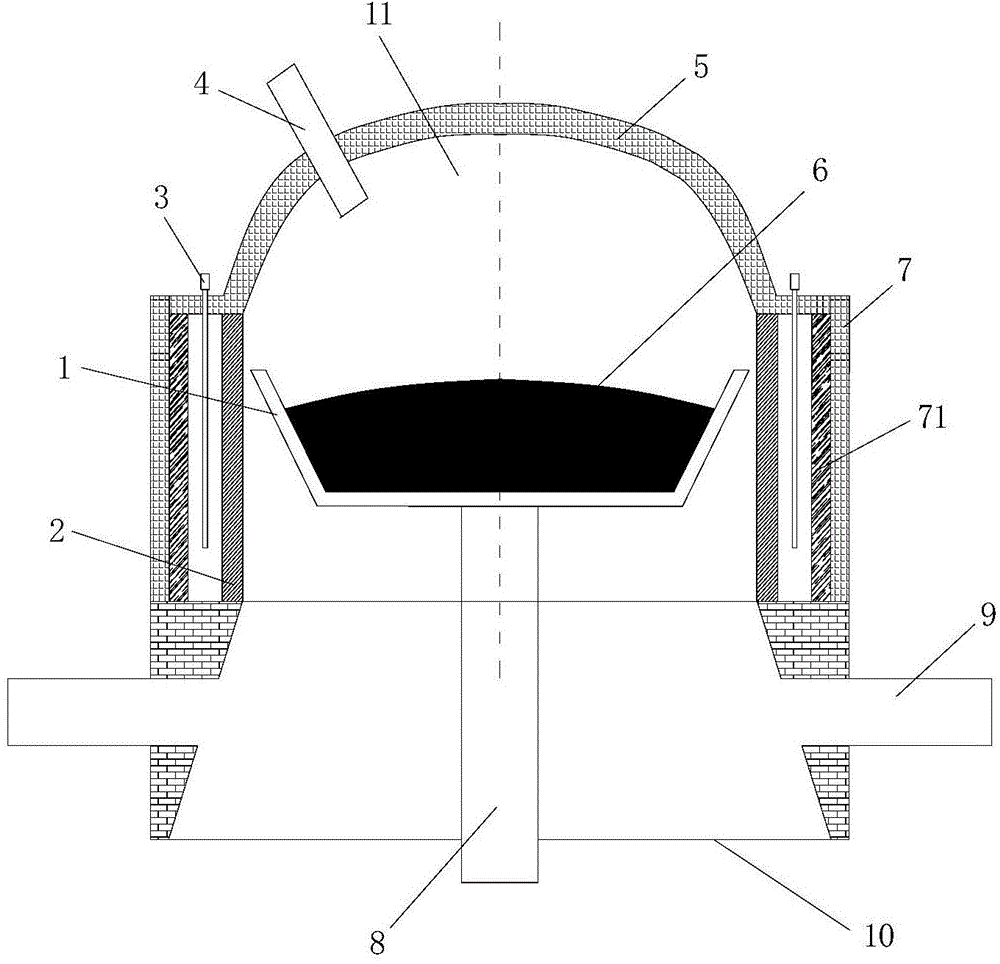
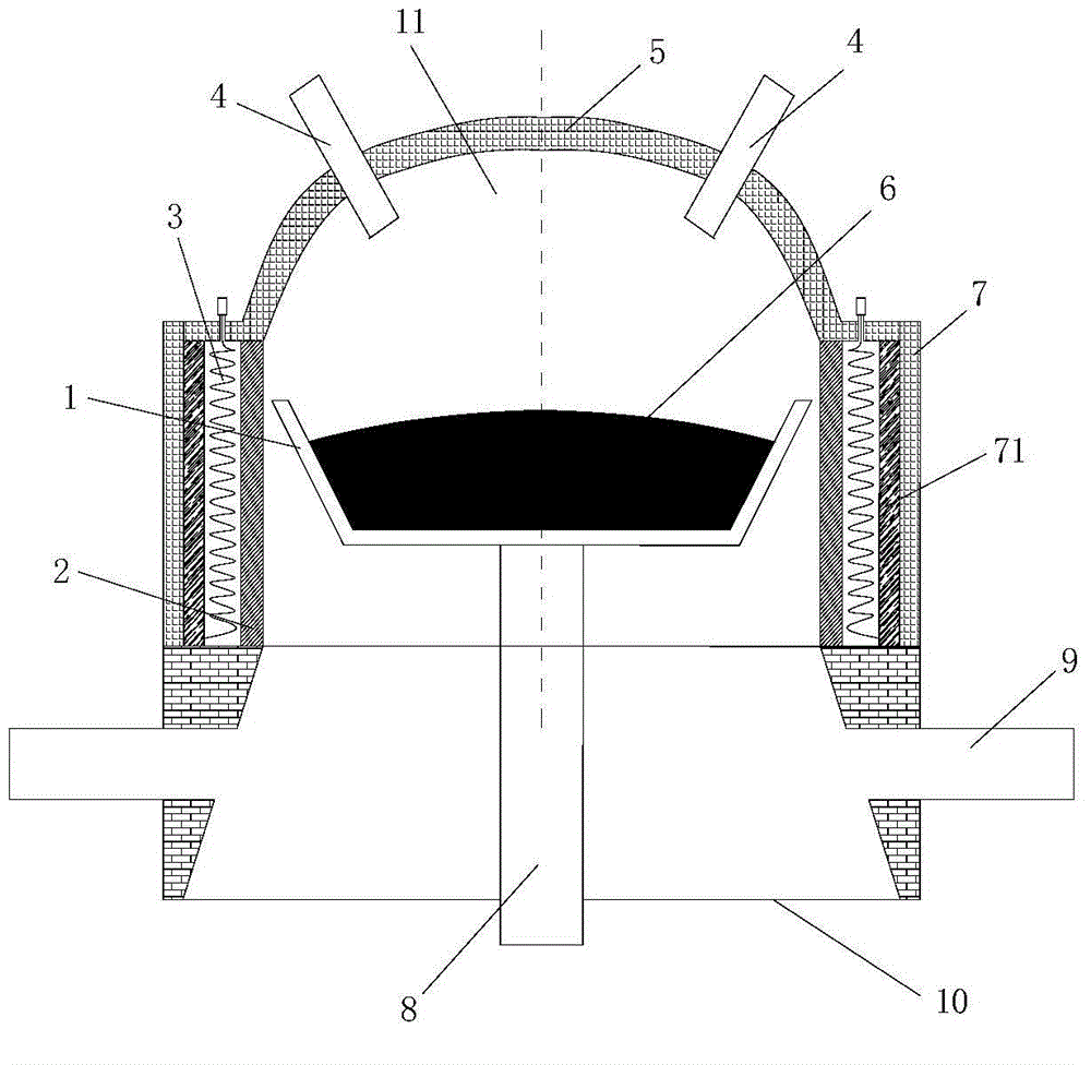
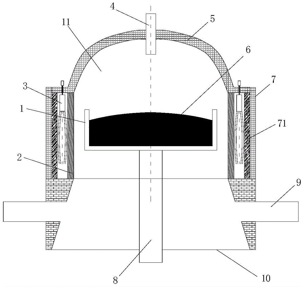
[0028] Figure 1 to Figure 3 It is a schematic structural diagram of deposition furnaces in different embodiments of the present invention. Such as Figure 1 to Figure 3 As shown, the deposition furnace for preparing synthetic quartz glass ingots includes:

[0029] Furnace body, the furnace body is made up of furnace roof 5, furnace wall 7 and furnace bottom 10, and furnace roof 5, furnace wall 7 and furnace bottom 10 encircle furnace hearth 11;

[0030] The burner 4 is arranged on the furnace roof 5;

[0031] The base rod 8 extends vertically from the furnace...


PUM


Abstract

The invention discloses a deposition furnace for manufacturing a synthetic quartz glass roller. The deposition furnace comprises a furnace body, a burner, a foundation pole and a deposition pool, wherein the furnace body is composed of a furnace top, a furnace wall and a furnace bottom, and a hearth is defined by the furnace top, the furnace wall and the furnace bottom; the burner is arranged on the furnace top; the foundation pole vertically extends into the hearth from the furnace bottom, can move in the vertical direction relative to the furnace body, and can rotate with the axis of the foundation pole as a rotating shaft; the deposition pool is arranged at the top of the foundation pole, is fixedly connected with the foundation pole, is defined by the bottom face and the lateral wall and serves as a deposition container of the quartz glass roller. According to the deposition furnace, component distribution coincidence of the quartz glass roller is improved, and the quartz glass roller with the uniform radial and axial structure is produced.

Description

technical field [0001] The invention relates to the technical field of preparation of quartz glass ingots, in particular to a deposition furnace for preparing synthetic quartz glass ingots. Background technique [0002] High-uniform synthetic quartz glass is an irreplaceable key basic material in high-tech fields such as aerospace, nuclear technology, lasers, and precision instruments. Optical inhomogeneity seriously affects the imaging quality of optical systems. [0003] At present, the melting methods of synthetic quartz glass ingot mainly include horizontal deposition furnace chemical vapor deposition method and vertical deposition furnace chemical vapor deposition method. Since the horizontal deposition furnace chemical vapor deposition method cannot produce large-sized, high-weight quartz glass ingots, and the furnace temperature is low, the energy consumption is large and the efficiency is low, it has been gradually replaced by the vertical deposition furnace chemical...

Claims


Application Information

Patent Timeline
IPC IPC(8): C03B20/00
Inventor 王玉芬聂兰舰向在奎饶传东王宏杰刘飞翔
Owner CHINA BUILDING MATERIALS ACAD
Features
  • R&D
  • Intellectual Property
  • Life Sciences
  • Materials
  • Tech Scout
  • Unparalleled Data Quality
  • Higher Quality Content
  • 60% Fewer Hallucinations
Learn More