Unlock instant, AI-driven research and patent intelligence for your innovation.
Device and method used for observing air flow field structure in environment of different degrees of vacuum
What is Al technical title?
Al technical title is built by PatSnap Al team. It summarizes the technical point description of the patent document.
A technology of vacuum degree and air flow, applied in the field of aerodynamics, can solve the problems of short action time and small action area, achieve the effect of simple and applicable device and method, and improve the probability of success and reliability
Active Publication Date: 2015-09-23
HARBIN INST OF TECH
View PDF5 Cites 17 Cited by
Summary
Abstract
Description
Claims
Application Information
AI Technical Summary
This helps you quickly interpret patents by identifying the three key elements:
Problems solved by technology
Method used
Benefits of technology
Problems solved by technology
[0003] Although laser-induced plasma ignition technology has many advantages over traditional ignition methods, such as no electromagnetic interference, non-invasive ignition, precise and controllable ignition position and time, multiple ignitions and multi-point simultaneous ignition, etc. The traditional ignition technology has a small action area and a short action time, so it is particularly important to choose a suitable ignition position to improve ignition reliability
Method used
Image
Click on the blue label to locate the original text in one second.
Reading with bidirectional positioning of images and text.
Examples
specific Embodiment approach 1
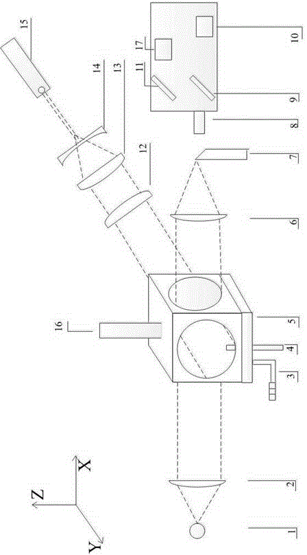
[0024] Specific implementation mode one: as figure 1 As shown, this embodiment provides a device for observing the structure of the air flow field under different vacuum environments, the device consists of a light source 1, a collimating mirror 2, a pressure transmitter 3, a gas nozzle 4, a vacuum chamber 5, a focusing Lens 6, knife edge 7, lens 8, high reflection lens 9, first CCD camera 10, total reflection mirror 11, focusing convex lens 12, collimating convex lens 13, plano-concave lens 14, laser 15, vacuum pump 16, the first Two CCD cameras 17 are formed, wherein: a light source 1, a collimating mirror 2, a vacuum chamber 3, a focusing lens 6, a knife edge 7, a lens 8, a high-reflective lens 9, a first CCD camera 10, and a full-reflective lens are arranged along the X-axis direction. The mirror 11 and the second CCD camera 17 are provided with a laser 15, a plano-concave lens 14, a collimating convex cylindrical lens 13, a focusing convex cylindrical lens 12, and a vacuu...
specific Embodiment approach 2
[0032] Embodiment 2: In this embodiment, the device described in Embodiment 1 can be used to observe the flow field structure of gas under different vacuum environments, which is realized by the following steps:
[0033] Step 1. Change the vacuum degree in the vacuum chamber 3 through the vacuum pump 5, and inject the airflow of the pre-mixed acetone gas into the vacuum chamber 3 through the gas nozzle 4;
[0034] Step 2: The light from the light source 1 forms collimated light through the collimating mirror 2 and passes through the observation area in the vacuum chamber 3, and the knife edge 7 is placed at the focal point of the focusing lens 6 to form a schlieren image;
[0035] Step 3, the laser beam is shaped into a sheet-like beam through the plano-concave lens 14, the collimating convex lens 13, and the focusing convex lens 12, and passes through the observation area in the vacuum chamber 3 to excite acetone molecules to generate fluorescence;
[0036] Step 4. Adjust the...
PUM
Abstract
The invention discloses a device and a method used for observing an air flow field structure in environment of different degrees of vacuum. The device is composed of a light source, a collimating lens, a pressure transmitter, a gas nozzle, a vacuum chamber, a focusing lens, a cut, a camera, a high reflectivity and high transmittance lens, a first CCD camera, a second CCD camera, a totally reflecting mirror, a focusing convex cylindrical lens, a collimating convex cylindrical lens, a plano-concave lens, a laser, a vacuum pump, a gas nozzle and a vacuum pump. According to the invention, a schlieren method and acetone PLIF are used to simultaneously observe the air flow field structure in environment of different degrees of vacuum; through the contrast correction of information acquired in two observing manners at the same time, a real air flow field structure is acquired; the success probability and the reliability of high altitude and space laser ignition are improved; the device and the method focus on observing the air flow field structure under different degrees of vacuum; and the air flow field structure information acquired through the device and the method can effectively help to choose the best ignition location for the laser ignition scheme of an engine in different environments.
Description
technical field [0001] The invention belongs to the field of aerodynamics, and relates to a device and a method for observing the structure of the air flow field under different vacuum degree environments. Background technique [0002] Today, with the deepening research on the ignition technology of aircraft turbine engines, military aircraft scramjet engines, rocket engines and aviationrocketattitude control and orbit control engines, in the face of many disadvantages of traditional ignition technology, laser plasma ignition technology and laser ignition Technology has become a very popular research topic, and this technology has great potential to replace the traditional spark ignition method. [0003] Although laser-induced plasma ignition technology has many advantages over traditional ignition methods, such as no electromagnetic interference, non-invasive ignition, precise and controllable ignition position and time, multiple ignitions and multi-point simultaneous ign...
Claims
Application Information
Patent Timeline
Application Date:The date an application was filed.
Publication Date:The date a patent or application was officially published.
First Publication Date:The earliest publication date of a patent with the same application number.
Issue Date:Publication date of the patent grant document.
PCT Entry Date:The Entry date of PCT National Phase.
Estimated Expiry Date:The statutory expiry date of a patent right according to the Patent Law, and it is the longest term of protection that the patent right can achieve without the termination of the patent right due to other reasons(Term extension factor has been taken into account ).
Invalid Date:Actual expiry date is based on effective date or publication date of legal transaction data of invalid patent.
