
A voltage transformer neutral point direct current suppression apparatus test system

A technology of transformer neutral point and DC current, applied in the field of testing, can solve the problems of transformer overheating, increased transformer consumption, increased transformer active power loss, etc.

Active Publication Date: 2015-09-23
XJ ELECTRIC +1
View PDF8 Cites 4 Cited by
  • Summary
  • Abstract
  • Description
  • Claims
  • Application Information

AI Technical Summary

Problems solved by technology

Harmonics lead to distortion of the system voltage waveform of the AC system, continuous overvoltage when the long line is closed with no load, relay protection malfunction, filter overload, increase in latent power supply current during single-phase reclosing, and increase in circuit breaker recovery voltage
DC bias can also lead to an increase in transformer excitation current, an increase in reactive power consumption by the transformer, overloading of the reactive power compensation device of the system or a drop in the system voltage
Another consequence of transformer bias saturation is to cause noise and vibration, and at the same time increase the active power loss of the transformer, which may cause local overheating of the transformer and cause damage

Method used


Image

  • A voltage transformer neutral point direct current suppression apparatus test system
  • A voltage transformer neutral point direct current suppression apparatus test system
  • A voltage transformer neutral point direct current suppression apparatus test system

Examples


Embodiment 1

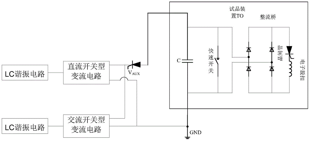
[0019] Such as figure 1 As shown, the transformer neutral point DC current suppression device test system of the present invention includes a DC charging unit, an AC charging unit, a trigger valve Vaux, an output terminal and a ground terminal; one end of the AC charging unit and the DC charging unit is connected to the output through the trigger valve Vaux The output terminal is used to connect with the high-voltage terminal of the test device TO; the other end of the AC charging unit and the DC charging unit are connected to the ground terminal, and the ground terminal is used to connect to the ground terminal of the test device TO and then grounded; the DC charging unit consists of The LC resonant circuit is composed of a DC switch-type converter circuit; the AC charging unit is composed of an LC resonant circuit and an AC switch-type converter circuit.

[0020] In the above embodiments, the AC charging unit includes a charging capacitor bank C 1 , Reactor L 1 , Trigger v...

Embodiment 2

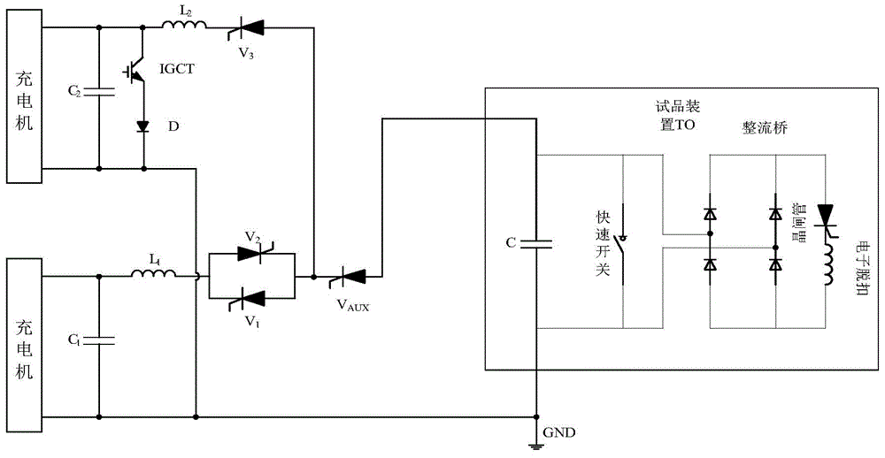
[0024] Such as image 3 As shown, the transformer neutral point DC current suppression device test system of the present invention includes a DC charging unit, an AC charging unit, a trigger valve Vaux, an output terminal and a ground terminal; one end of the AC charging unit and the DC charging unit passes through the trigger valve Vaux Connect the output terminal, the output terminal is connected to the high voltage terminal of the test device TO; the other end of the AC charging unit and the DC charging unit are connected to the ground terminal, and the ground terminal is connected to the ground terminal of the test device TO and grounded.

[0025] The AC charging unit includes a charging capacitor bank C 1 , Reactor L 1 , Trigger valve V 1 and trigger valve V 2 , triggers the valve V 1 and trigger valve V 2 anti-parallel. Charging capacitor bank C 1 sequentially through the reactor L 1 , anti-parallel trigger valve V 1 and trigger valve V 2 Connect trigger valve ...


PUM


Abstract

The invention relates to a voltage transformer neutral point direct current suppression apparatus test system comprising a direct current charging unit, an alternating current charging unit, a trigger valve Vaux, an output terminal and a grounding terminal. One terminal of the alternating current charging unit and one terminal of the direct current charging unit are connected to the output terminal through the trigger valve Vaux. The output terminal is used for connection to a high-voltage terminal test device TO. The other terminal of the alternating current charging unit and the other terminal of the direct current charging unit are connected to the grounding terminal. The grounding terminal is used for grounding after being connected to a grounding terminal of the test device. The direct current charging unit is composed of an LC resonance circuit and a direct current switching mode convertor circuit. The alternating current charging unit is composed of an LC resonance circuit and an alternating current switching mode convertor circuit. A recombination current corresponding to an actual working condition is generated by means of recombining an alternating current with a direct current. The recombination current is then applied to the test device to carry out corresponding examining, so that testing of the current and voltage stress of a voltage transformer neutral point direct current suppression apparatus is realized.

Description

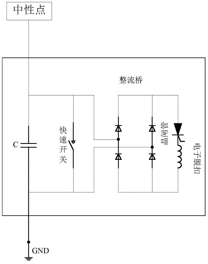
technical field [0001] The invention belongs to the field of testing, and in particular relates to a testing system for a neutral point direct current suppressing device of a transformer. Background technique [0002] When the DC transmission system operates in the single-pole ground return mode, it will cause a DC potential near the ground electrode of the DC transmission system converter station, which is determined by the magnitude of the DC current injected into the ground electrode and the soil resistivity. The injection current is the DC transmission current, and the higher the soil resistivity, the higher the potential, and the wider the range of influence. The high potential of the DC grounding electrode will affect the ground grid potential of the AC substation, causing a DC current to flow through the transformer running at the neutral point of the AC substation; that is, it is equivalent to shunting part of the DC transmission current, and the DC current flowing t...

Claims


Application Information

Patent Timeline
IPC IPC(8): G01R31/00
Inventor 常忠廷张坤胡永雄李娟才利存徐涛董意峰
Owner XJ ELECTRIC
Learn More