Dust and mist removal device, treatment tower and its application

A technology for demisting device and flue gas treatment, which is applied in the direction of combination device, dispersed particle separation, chemical instruments and methods, etc., can solve the problems of power consumption, increase the difficulty of water balance of desulfurization system, increase operating cost, etc., and achieve demisting. Efficiency improvement, excellent dust removal and defogging effect, and the effect of saving equipment and operating costs

Active Publication Date: 2016-07-20
ZHONGJING ENVIRONMENTAL TECH CO LTD
View PDF7 Cites 0 Cited by
  • Summary
  • Abstract
  • Description
  • Claims
  • Application Information

AI Technical Summary

Problems solved by technology

However, the wet electrostatic precipitator is placed behind the desulfurization tower, which will increase resistance. It uses closed-loop flushing water, which needs to continuously replenish raw water and discharge waste water, which increases the difficulty of water balance in the desulfurization system. The technical cost of a single product of the wet electrostatic precipitator High, the equipment investment cost is higher than that of ordinary electrostatic precipitators, and in addition to the power consumption of the dust collector itself, the auxiliary circulating water pump will also consume part of the electricity during operation, and the additives in the flushing water will also increase part of the operating cost, so its input and operating costs are too expensive

Method used


Image

  • Dust and mist removal device, treatment tower and its application
  • Dust and mist removal device, treatment tower and its application
  • Dust and mist removal device, treatment tower and its application

Examples


Embodiment 1

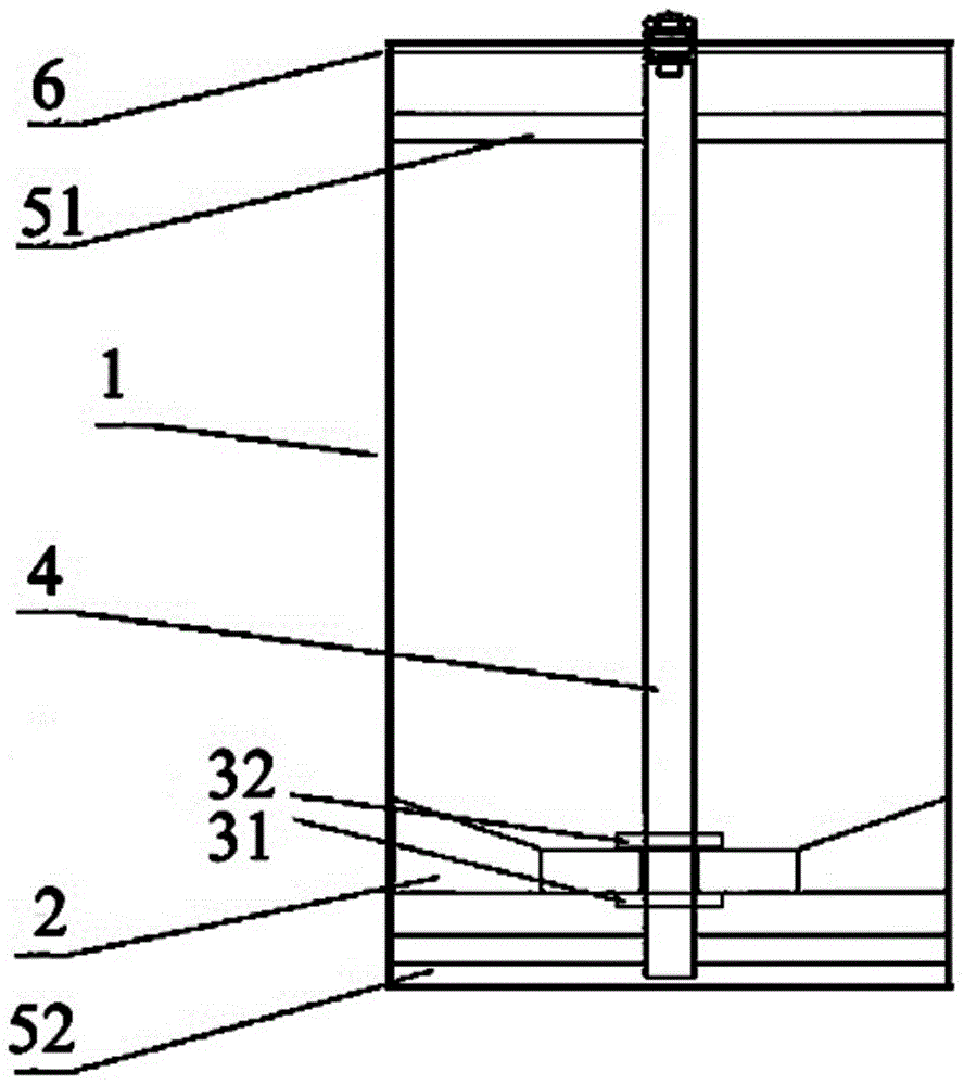
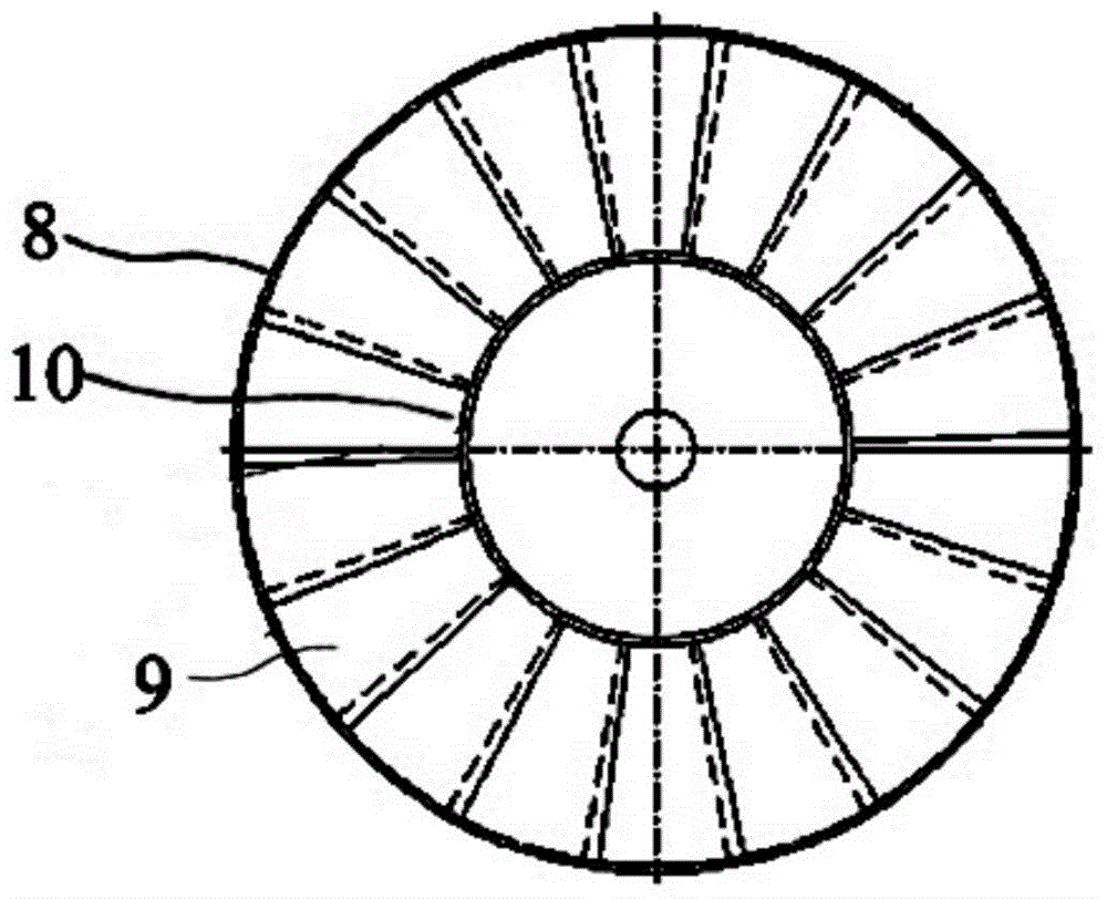
[0060] figure 1 It is a schematic diagram of the dust removal and mist removal device of the present invention, figure 2 Schematic diagram of a rotating vane set. The dust and mist removal device of the present invention includes a cylindrical guide tube 1, a center axis 4 is arranged on the center axis of symmetry inside the guide tube 1, and the center axis 4 passes through a first hub 51 and a second hub 52 It is fixed together with the guide tube 1, wherein the first hub 51 is a hollow structure, which is bonded and fixed with the central shaft 4 and the guide tube 1 respectively, and the second hub 52 is a solid structure, which is bonded and fixed with the central shaft 4. It is fixed with the guide tube 1 by screws.

[0061] A layer of rotating vane sets 2 is provided at the lower part of the guide tube 1 . The rotating blade set 2 includes an outer cylinder 8 , a blade set 9 and a central cylinder 10 . The outer cylinder 8 and the central cylinder 10 are fixedly c...

Embodiment 2

[0064] Change the angle of elevation of all blades to be 45°, and other conditions are the same as in Example 1.


PUM

PropertyMeasurementUnit
angleaaaaaaaaaa
angleaaaaaaaaaa
angleaaaaaaaaaa

Abstract

The invention discloses a dedusting and demisting device, a treatment tower and a use of the dedusting and demisting device. The dedusting and demisting device comprises a guide cylinder, a middle shaft and a rotating blade group located in the guide cylinder, and a retaining ring arranged at the upper part of the guide cylinder. The rotating blade group comprises a center cylinder, a blade group and an outer cylinder. The rotating blade group is located in the guide cylinder. The middle shaft sleeves the center cylinder. The center cylinder and the outer cylinder are arranged coaxially. The blade group comprises multiple blades. One end of each one of the blades is fixedly connected to the center cylinder and the other end is fixedly connected to the outer cylinder. The blades are inclinedly arranged and have elevation angles of 20-60 degrees. The dedusting and demisting device can completely replace the conventional demister in the existing desulfurization tower and a wet type electric precipitator in the rear of the desulfurization tower, has excellent dedusting and demisting effects and reduces equipment and operation costs.

Description

technical field [0001] The invention relates to a dust and fog removal device, a processing tower and its use, in particular to a dust and fog removal device, a flue gas treatment tower and its use for dust and mist-laden flue gas after dust removal and desulfurization. Background technique [0002] China is a large coal-based energy consumer, but also a major steel producer. A large amount of dust, sulfur dioxide, nitrogen oxides and other harmful substances will be produced in the process of coal burning and smelting. If the dust is not treated, it will enter the atmosphere with the flue gas, seriously affecting the visibility and air quality of the atmosphere, and sulfur dioxide is even more harmful. [0003] At present, the dust removal technologies applied to coal-fired power plants and sintering machines are mainly electrostatic dust removal and bag dust removal. The electrostatic dust removal efficiency is greater than 10, and the dust removal efficiency of the corre...

Claims


Application Information

Patent Timeline
Patent Type & Authority Patents(China)
IPC IPC(8): B01D45/14B01D50/00B01D53/78B01D53/14B01D53/00B01D53/48B01D53/60B01D53/64
Inventor 童裳慧
Owner ZHONGJING ENVIRONMENTAL TECH CO LTD
Why Eureka
Try Eureka