Technology for plating carbon film on surface of capillary glass tube

一种毛细玻璃管、镀碳膜的技术,应用在金属材料涂层工艺、气态化学镀覆、涂层等方向,达到减小能量损失、实现局部加热的效果

Active Publication Date: 2015-09-30
LASER RES INST OF SHANDONG ACAD OF SCI
View PDF6 Cites 7 Cited by
  • Summary
  • Abstract
  • Description
  • Claims
  • Application Information

AI Technical Summary

Problems solved by technology

[0003] In the process of oilfield development, it is necessary to monitor downhole temperature, pressure and other parameters in real time to understand the physical state of the downhole to optimize the oil recovery plan and improve oil recovery efficiency. Due to the harsh environment downhole, traditional electronic sensors cannot work stably for a long time downhole. Optical fiber Sensors are more and more widely used due to their strong anti-interference ability, corrosion resistance, and good reliability.

Method used


Image

  • Technology for plating carbon film on surface of capillary glass tube
  • Technology for plating carbon film on surface of capillary glass tube
  • Technology for plating carbon film on surface of capillary glass tube

Examples


Embodiment 1

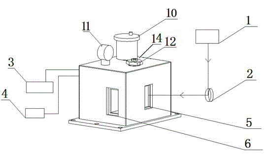
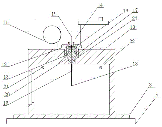
[0032] Such as Figure 1-2 As shown, a carbon coating device on the surface of a capillary glass tube includes a carbon dioxide laser marking machine 1 fixed on a base and a prism 2 cooperating with the carbon dioxide laser marking machine 1, and also includes a hollow shell 8. One side of the housing 8 is provided with a light-transmitting window corresponding to the prism 2, and the other side of the housing 8 is provided with a first air hole 21 and a second air hole 22, the first air hole 21 communicates with the vacuum pump 3, and the second air hole 22 communicates with the vacuum pump 3. The acetylene nitrogen gas tank 4 is in communication; the housing 8 is provided with an optical fiber clamp 14 , and the inside of the housing 8 is hermetically sealed from the outside of the housing 8 .

[0033] The heating temperature of the capillary glass tube 18 can be adjusted by setting the marking length, laser intensity and time of the carbon dioxide laser marking machine 1; ...

Embodiment 2

[0040] The similarities between this embodiment and Embodiment 1 will not be repeated, the difference is that it is a process for coating the surface of a capillary glass tube with a carbon film, and it uses the device for coating a carbon film on the surface of a capillary glass tube described in Embodiment 1. , which includes the following steps:

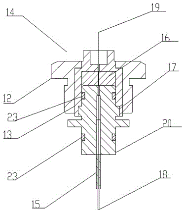
[0041] (1) Build the carbon coating device on the surface of the capillary glass tube, fix the housing 8 on the position moving platform 7, put the rubber gasket 16 between the middle sleeve 13 and the collimating glass tube fixing seat 20, and carbon coating will be required The capillary glass tube 18 of the film is placed in the collimating glass tube 15 at the bottom of the optical fiber holder 14, the pigtail 19 passes through the rubber gasket 16, tightens the fastening nut 12, compresses the middle sleeve 13 and the rubber gasket 16, and puts the middle sleeve 13 The relative position to the housing 8 is marked, and the vac...


PUM

PropertyMeasurementUnit
lengthaaaaaaaaaa

Abstract

The invention provides a device and a technology for plating the surface of a glass capillary tube with a carbon film. The device comprises a carbon dioxide laser printer fixed on a base and a prism matched with the carbon dioxide laser printer and further comprises a hollow casing, wherein a light transmitting window corresponding to the prism is formed in one side surface of the casing, a first gas hole and a second gas hole are formed in the other side surface of the casing, the first gas hole is communicated with a vacuum pump, and the second gas hole is communicated with an acetylene and nitrogen gas tank; an optical fiber clamp is arranged on the casing, and the inner part of the casing is hermetically sealed with the outer part of the casing. The carbon film plating device is suitable for carrying out carbon film deposition on the surface of the glass capillary tube in a chemical vapor deposition method. The glass capillary tube needing to plated with the film is inserted in a collimated glass tube, a tail fiber on the tail is tightened and sealed through a rubber pad, the optical fiber clamp, an optical fiber fixing clamp and a nut, and two turriform joint devices are respectively connected with the vacuum pump and the gas tank. The glass capillary tube coated with the carbon film can effectively prevent the corrosion of hydrogen ions in an external environment. The service life of the glass capillary tube is prolonged.

Description

[0001] This application is a divisional application of a Chinese invention patent application with an application date of September 16, 2014, an application number of 2014104703203, and a Chinese invention patent application entitled Device and Process for Carbon Coating on the Surface of Capillary Glass Tubes. technical field [0002] The invention belongs to the technical field of optical fiber sensors, and relates to a method for preventing hydrogen damage of optical fiber sensors, in particular to a film coating device and process on the surface of a capillary glass tube. Background technique [0003] In the process of oilfield development, it is necessary to monitor downhole temperature, pressure and other parameters in real time to understand the physical state of the downhole to optimize the oil recovery plan and improve oil recovery efficiency. Due to the harsh environment downhole, traditional electronic sensors cannot work stably for a long time downhole. Optical fib...

Claims


Application Information

Patent Timeline
Patent Type & Authority Applications(China)
IPC IPC(8): C23C16/26C23C16/46
Inventor 王英英王昌刘小会赵庆超马龙
Owner LASER RES INST OF SHANDONG ACAD OF SCI
Why Eureka
Try Eureka