Reflective gas sensing system based on hollow-core photonic crystal fiber

A hollow-core photonic crystal and gas sensing technology, which is applied in material analysis, measuring devices, instruments, etc. through optical means, can solve the problem of high stability and position accuracy, unfavorable optical signal remote transmission and control, Increase light transmission loss and other issues to achieve high sensitivity, increase effective distance, and improve sensitivity

Inactive Publication Date: 2015-09-30
NORTHEASTERN UNIV
View PDF3 Cites 15 Cited by
  • Summary
  • Abstract
  • Description
  • Claims
  • Application Information

AI Technical Summary

Problems solved by technology

However, considering the practical application, connecting the hollow-core photonic crystal fiber to the optical fiber sensing system needs to be coupled with the ordinary fiber. If the traditional fusion splicing technology is used to connect the hollow-core photonic crystal fiber and the ordinary fiber, the gas to be measured will not be able to Into the inside of the fiber core, although the laser drilling technology is used to punch holes in the cladding of the photonic crystal fiber, so that the gas to be measured flows into the fiber core, but this will also cause light leakage and increase the transmission loss of light. If mechanically aligned The method realizes the coupling between the hollow-core photonic crystal fiber and the ordinary fiber. Since there will be a gap between the two, it can facilitate the gas to be measured to flow into the fiber core while realizing the coupling, but

Method used


Image

  • Reflective gas sensing system based on hollow-core photonic crystal fiber
  • Reflective gas sensing system based on hollow-core photonic crystal fiber

Examples


Embodiment Construction

[0021] In order to make the object, technical solution and advantages of the present invention clearer, the specific structure of the present invention will be further described in detail below in conjunction with specific embodiments and with reference to the accompanying drawings.

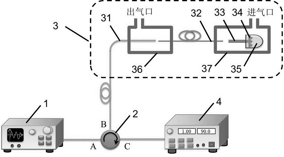
[0022] The invention proposes a reflective gas sensing system based on a hollow-core photonic crystal fiber, and uses the photonic crystal fiber as a gas chamber to realize all-fiber gas measurement. gas sensing systems such as figure 1As shown, its working process is as follows: the optical signal emitted from the light source 1 first enters the port A of the circulator 2, and then outputs from the port B of the circulator 2 into the sensing probe 3 for gas measurement. When the optical signal passes through the sensing probe respectively After the single-mode optical fiber 31, the hollow-core photonic crystal optical fiber 32, and the multimode optical fiber 33 in 3, reflection will be generate...


PUM

PropertyMeasurementUnit
Opening widthaaaaaaaaaa
Outer diameteraaaaaaaaaa
The inside diameter ofaaaaaaaaaa

Abstract

The invention provides a reflective gas sensing system based on a hollow-core photonic crystal fiber. The reflective gas sensing system consists of a light source 1, a circulator 2, a sensing probe 3 and a spectrum demodulation unit 4, and is characterized in that light signals emitted by the light source 1 enter a port A of the circulator 2 at first and are then output from a port B of the circulator 2 to enter the sensing probe 3; when sequentially passing through a single-mode fiber 31, a hollow-core photonic crystal fiber 32 and a multi-mode fiber 33 in the sensing probe 3, the light signals are reflected at a high-reflectivity mirror 34 at the tail end of the multi-mode fiber 33, and the reflected signals sequentially pass through the multi-mode fiber 33, the hollow-core photonic crystal fiber 32 and the single-mode fiber and then return to the port B of the circulator 2, and after that, are output from a port C of the circulator 2 to enter the spectrum demodulation unit 4 for data processing, so that the concentration of a gas to be detected in the hollow-core photonic crystal fiber 32 can be calculated. The invention provides a feasible method for remote real-time on-line monitoring of a gas sensor based on the hollow-core photonic crystal fiber.

Description

technical field [0001] The invention relates to a reflective gas sensing system based on a hollow-core photonic crystal fiber, and belongs to the technical field of micro-optoelectronic devices. Background technique [0002] In recent decades, with the development of industry, a large amount of toxic, harmful and even flammable and explosive gases have seriously polluted the human living environment [Document 1. G. Schurmann, K. Schafer, C. Jahn, et al. The impact of NO x , CO and VOC emissions on the air quality of Zurich airport[J]. Atmospheric Environment, 2007, 41(1): 103-118.]. For some toxic and harmful gases, it is necessary to detect very low concentrations. Therefore, it is of great significance to achieve high-accuracy and high-sensitivity detection of trace gases [Document 2. L Melo, G. Burton, B. Davies, et al. Highly sensitive coated long period grating sensor for CO 2 detection at atmospheric pressure[J]. Sensors and Actuators B: Chemical, 2014, 202: 294-30...

Claims


Application Information

Patent Timeline
IPC IPC(8): G01N21/17
Inventor 赵勇张亚男
Owner NORTHEASTERN UNIV
Why Eureka
Try Eureka