IGBT module packaging structure of inverter

A module packaging and inverter technology, applied in the direction of electric solid-state devices, semiconductor devices, electrical components, etc., can solve the problems of reduced current capacity, complex phase outlets, high failure rate, etc., and achieve the reduction of common-mode interference current to ground and the Effects of improved capacity and lifetime, and reduced equivalent parasitic capacitance

Active Publication Date: 2015-09-30
UNITED AUTOMOTIVE ELECTRONICS SYST
View PDF6 Cites 5 Cited by
  • Summary
  • Abstract
  • Description
  • Claims
  • Application Information

AI Technical Summary

Problems solved by technology

The current capability of the small bonding wire is very weak, and often when the semiconductor IGBT chip is not overheated (Tj<150 degrees), the current has been limited by the bonding wire
[0008] like Figure 4 As shown, the conventional IGBT module cooling treatment method is to flatten the flat half-bridge IGBT module with large area and small thickness on the water cooling plate. far apart
In order to facilitate customer wiring, it is usually required that the three-phase output lines of the inverter IGBT module are adjacent to each other. The phase outgoing lines of the IGBT module need to be routed and bent for a long time. rise, making the working environment of electronic components harsh
The positive and negative busbars of the three-phase half-bridge IGBT module are far apart, and three pairs of busbar capacitors are required to connect with them to ensure a small parasitic inductance. There are many connection procedures, complex production, and high failure rate.
The three-phase half-bridge IGBT module needs a large area of ​​water-cooled board to cover, and the conventional water-cooled board is thick and heavy, which limits the power density of the inverter
The water channels of the three-phase half-bridge IGBT modules are connected in series, and the first two-phase half-bridge IGBT modules are heated. When the water flows through the third-phase half-bridge IGBT modules, the water temperature has risen sharply, which reduces the current capacity.

Method used


Image

  • IGBT module packaging structure of inverter
  • IGBT module packaging structure of inverter
  • IGBT module packaging structure of inverter

Examples


Embodiment 1

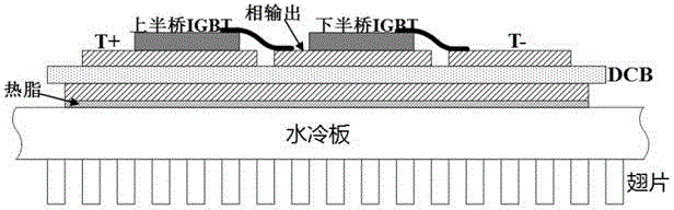
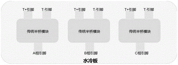
[0040] Inverter IGBT (Insulated Gate Bipolar Transistor) module package structure, such as Figure 5 , Figure 6 As shown, the inverter IGBT module includes three half-bridge IGBT modules of phase A, phase B and phase C, and each half-bridge IGBT module includes an upper half-bridge IGBT chip and a lower half-bridge IGBT chip, a first insulating ceramic substrate (DCB ), the second insulating ceramic substrate (DCB);

[0041] The surface area of ​​the first insulating ceramic substrate is provided with a positive input terminal (T+) area and a negative input terminal (T-) area, and the positive input terminal (T+) area and the negative input terminal (T-) area are insulated from each other;

[0042] Each IGBT chip has three electrodes C, E, and G, of which the two electrodes C and E are used to conduct current, and G is the on / off control pin of the IGBT;

[0043] The lower surface of the upper half-bridge IGBT chip is the C pole, and the upper surface is the E pole;

[004...

Embodiment 2

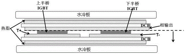
[0055] Based on the inverter IGBT (insulated gate bipolar transistor) module packaging structure of the first embodiment, such as Figure 7 As shown, the A-phase, B-phase and C-phase three half-bridge IGBT modules of the inverter IGBT module are arranged between three compartments formed by four identical water-cooled plates and clamped by the water-cooled plates.

[0056] In the packaging structure of the inverter IGBT module in Embodiment 2, both sides of the half-bridge IGBT module of each phase contact the water-cooled plate through thermal grease to form a double-sided heat dissipation structure, which is equivalent to two thermal resistances connected in parallel in thermodynamics, which can realize double-sided cooling , so the thermal resistance is only half of the traditional single-sided cooling system.

Embodiment 3

[0058] The package structure of the inverter IGBT (insulated gate bipolar transistor) module based on the second embodiment, such as Figure 8 As shown, 4 identical water-cooled plates are fastened together through four screws at the four corners.

[0059] Preferably, the water cooling plate is provided with a water inlet at the top and a water outlet at the bottom, the water inlets of each water cooling plate are respectively connected to the water inlet pipes, and the water outlets are respectively connected to the water outlet pipes.

[0060] Preferably, the water inlet and outlet pipes are sealed with the corresponding water inlet and outlet by O-rings.

[0061] Preferably, the water cooling plate is made of thin aluminum sheets, and folds or protrusions can be provided inside the water cooling plate to increase the heat dissipation area.

[0062] In the packaging structure of the inverter insulated gate bipolar transistor module of the third embodiment, the water flow en...


PUM


Abstract

The invention discloses an IGBT module packaging structure of an inverter. The positive input end and the negative input end of each half-bridge IGBT module are respectively arranged on the lower surface of a chip. A buffer capacitor can be respectively welded on the surfaces of the positive input end area and the negative input end area on the surface of a first insulation ceramic substrate, thereby maximally eliminating pin inductance of the IGBT module through short-circuit. An E pole of an upper half-bridge IGBT chip and a C pole of the lower half-bridge IGBT chip of each half-bridge IGBT module are respectively arranged on the upper surface of the chip, and can be located far from a water cooling board, thereby reducing an equivalent parasitic capacitance, reducing earth common-mode interference current, and improving EMC performance of the inverter. A binding line of each phase half-bridge IGBT module is saved, thereby improving current capability and prolonging service life time, reducing chip area and lowering inverter cost. Electric pins of each phase half-bridge IGBT module are directly welded on the insulation ceramic substrate and a chip. The distances among the positive input end, the negative input end and phase output pin of each phase half-bridge IGBT module are small, thereby realizing short outlet wire of the inverter, simplifying wiring and ensuring no easy heating of an inner chamber by copper bars.

Description

technical field [0001] The invention relates to a motor inverter, in particular to an inverter IGBT module packaging structure. Background technique [0002] Electric vehicles have gradually entered the automotive market due to fuel saving and environmental protection. The motor controller (inverter) is the core component of electric vehicles, which together with the motor constitute the "engine" of new energy vehicles. has a huge impact on performance. [0003] The core component in the inverter, the IGBT (Insulated Gate Bipolar Transistor, insulated gate bipolar transistor) module accounts for more than 40% of the cost and more than 90% of the heat generation. The quality of its packaging and mechanical heat dissipation layout have a great impact on performance of the entire inverter. [0004] Such as figure 1 As shown, each half-bridge IGBT module contains two IGBT chips, the upper and lower half-bridges, and each IGBT chip has three electrodes C, E, and G, where C and...

Claims


Application Information

Patent Timeline
Patent Type & Authority Applications(China)
IPC IPC(8): H01L25/07H01L25/00
CPCH01L2924/13055H01L2924/19107H01L2224/48472H01L2224/49111H01L2224/49175H01L2924/00
Inventor 孙儒文王向炜范昊
Owner UNITED AUTOMOTIVE ELECTRONICS SYST
Why Eureka
Try Eureka