Three-phase power grid disturbance generating device and control method thereof

A three-phase power grid and generating device technology, applied in circuit devices, harmonic reduction devices, electrical components, etc., can solve the problems of being difficult to be suitable for mobile vehicle-mounted on-site detection applications, bulky, and high manufacturing costs, so as to reduce the overall The complexity and number of components, the simplicity of the system structure, the effect of balancing switching losses

Active Publication Date: 2015-09-30
SHENZHEN HOPEWIND ELECTRIC CO LTD
View PDF4 Cites 15 Cited by
  • Summary
  • Abstract
  • Description
  • Claims
  • Application Information

AI Technical Summary

Problems solved by technology

[0005] One of the technical problems to be solved by the present invention is to provide a three-phase power grid disturbance generating device, which overcomes the defects of the existing three-phase power grid disturbance generating device, which are bulky, difficult to meet the requirements of mobile vehicle-mounted on-site detection applications, and high manufacturing costs
[0006] The second technical problem to be solved by the present invention is to provide a control method for a three-phase power grid disturbance generating device, which overcomes the problems that the existing three-phase power grid disturbance generating device is bulky, difficult to meet the requirements of mobile vehicle-mounted on-site detection applications, and has high manufacturing costs. defect

Method used


Image

  • Three-phase power grid disturbance generating device and control method thereof
  • Three-phase power grid disturbance generating device and control method thereof
  • Three-phase power grid disturbance generating device and control method thereof

Examples


Embodiment Construction

[0035] The present invention will be further described below in conjunction with the accompanying drawings and embodiments.

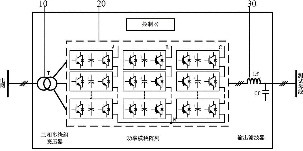
[0036] Such as figure 2 , image 3 As shown, the three-phase grid disturbance generating device of the present invention includes a three-phase multi-winding transformer 10 , a power module array 20 and an output filter 30 .

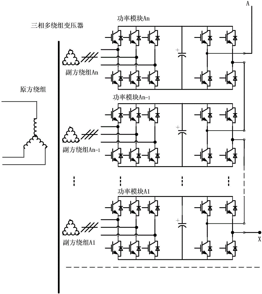
[0037] The primary side of the three-phase multi-winding transformer 10 is connected to the three-phase medium and high voltage grid, and the secondary side is multiple sets of three-phase windings. The power module array 20 includes 3 groups of power modules, each group of power modules corresponds to a certain output phase, and each group of power modules includes no less than 2 power modules. Such as Figure 7As shown, each power module includes a three-phase PWM rectifier 21, a DC bus link 22 and a single-phase H-bridge inverter 23, and the input of the three-phase PWM rectifier 21 is connected to the corresponding seconda...


PUM


Abstract

The invention discloses a three-phase power grid disturbance generating device and a control method thereof. The device comprises a three-phase multi-winding transformer, a power module array and an output filter which are connected sequentially, wherein the power module array comprises three groups of power modules corresponding to three-phase output; each power module comprises a three-phase PWM (pulse-width modulation) rectifier, a DC (direct-current) bus link and a single-phase H-bridge inverter which are connected sequentially; input of the three-phase PWM rectifiers is connected with secondary-side three-phase windings corresponding to the three-phase multi-winding transformer; each DC bus link comprises a DC capacitor group; output ends of the single-phase H-bridge inverters are cascaded to form device basic output; each group of power modules comprise at least one low-frequency disturbance generating power module for outputting fundamental waves or outputting the fundamental waves and harmonic waves as well as at least one high-frequency disturbance generating power module for outputting the harmonic waves. The device is controlled with the method. According to the method, the switching frequency of the at least one high-frequency disturbance generating power module is controlled to be not smaller than that of the at least one low-frequency disturbance generating power module. The device is small in size, low in cost and capable of meeting mobile, vehicle-mounted and on-site detection requirements.

Description

technical field [0001] The invention relates to a three-phase grid disturbance generating device used for grid adaptability detection, and also relates to a control method of the device. Background technique [0002] With the wide application of various electrical equipment such as power generation, transmission and consumption, grid adaptability has become an important content of electrical equipment testing. Grid adaptability detection usually includes detection of grid voltage, frequency deviation and flicker, grid voltage unbalance, etc. A more complete grid adaptability detection also includes detection of grid harmonic adaptability. Due to the great contingency and uncontrollability of the deviation and distortion of the power grid, the grid adaptability detection generally needs to be equipped with a special three-phase grid disturbance generator. The output voltage of the three-phase power grid disturbance generating device with harmonic output capability can be div...

Claims


Application Information

Patent Timeline
Patent Type & Authority Applications(China)
IPC IPC(8): H02J3/00H02J3/01
CPCY02E40/40
Inventor 周党生谢磊盛小军
Owner SHENZHEN HOPEWIND ELECTRIC CO LTD
Why Eureka
Try Eureka