
Method and system for low energy consumption sewage treatment with two stages of pretreatment and micro aeration

A technology of sewage treatment system and sewage treatment method, applied in water/sludge/sewage treatment, chemical instruments and methods, water/sewage multi-stage treatment, etc. Complete and other problems, to achieve the effect of microbial stability and long doubling time

Inactive Publication Date: 2015-10-07
北京益文科技有限公司
View PDF5 Cites 9 Cited by
  • Summary
  • Abstract
  • Description
  • Claims
  • Application Information

AI Technical Summary

Problems solved by technology

In addition, in the previous treatment process, part of the nitrogen element was removed through the absorption of ammonia nitrogen by the microorganism's own growth needs. In fact, it did not leave the sewage plant, but was transferred to the sludge, and released into the digestive juice during the sludge treatment process. In the process, the digestive juice is returned to the sewage treatment process, which increases the treatment burden
On the other hand, due to the low carbon and nitrogen ratio in sewage, conventional processes often show incomplete denitrification, which makes it difficult to completely remove nitrogen in sewage, or thus adding additional carbon sources increases the operating costs of sewage plants
In addition, due to the need for the sewage to experience different environments, the sewage is continuously distributed and returned throughout the treatment process. There are too many control factors and the operation process is extremely complicated.

Method used


Image

  • Method and system for low energy consumption sewage treatment with two stages of pretreatment and micro aeration

Examples


Embodiment Construction

[0020] The present invention will be further described below in conjunction with the accompanying drawings and embodiments.

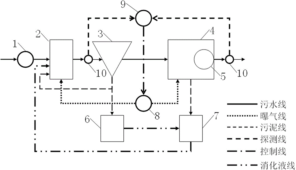
[0021] Such as figure 1 As shown, the principle diagram of the two-stage low-energy sewage treatment system adopting pretreatment and micro-aeration of the present invention is provided, which includes a regulating tank 1, a pretreatment tank 2, a pretreatment sedimentation tank 3, a denitrification tank 4, Membrane filter module 5, sludge digestion tank 6, denitrification sludge storage tank 7, blower 8, controller 9 and detector 10, the adjustment tank 1 shown is located at the front end of the pretreatment tank 2, domestic sewage first enters the adjustment tank In 1, the regulating pool 1 adjusts the water quality and water quantity, reduces the misunderstanding of the fluctuation of water quality and water quantity in the treatment process, and coordinates the constant flow of the entire sewage treatment system.


PUM


Abstract

The invention provides a method for low energy consumption sewage treatment with two stages of pretreatment and micro aeration, and the method comprises the following steps: a) pretreatment of sewage, that is adsorption of organic matters and suspension substances in sewage by microorganisms; b) settlement of sewage; c) denitrification of sewage, that is transformation of ammonia nitrogen in the sewage into nitrite nitrogen by nitrite bacteria, and transformation of ammonia nitrogen and nitrite nitrogen into nitrogen at the same time by anaerobic ammonium oxidation bacteria for realizing denitrification. A sewage treatment system provided by the invention comprises a pretreatment pool, a pretreatment sedimentation basin, a denitrification pool, a blower, a controller and a detector; the blower is used for realizing aeration, and the detector is used for detecting water quality, and the controller controls the operation of the sewage treatment system. The sewage treatment system and method provided by the invention transform most nitrogen elements into nitrogen by using denitrification of the anaerobic ammonium oxidation bacteria, so that the nitrogen element is departed from the water body and pollutants indeed. During a sludge treatment phase, organic matters are transformed into energy by anaerobic fermentation, and the energy can considerably supplement the electric quantity consumption of the sewage factory itself, and the activity of the denitrifying bacteria is kept.

Description

technical field [0001] The invention relates to a two-stage low-energy sewage treatment method and system using pretreatment and micro-aeration. An inorganic sewage treatment method and system for anaerobic fermentation. Background technique [0002] The concentration of ammonia nitrogen in my country's urban sewage is generally too high, resulting in a carbon-to-nitrogen ratio lower than 4. The biological denitrification process of sewage includes three processes of ammonification, nitrification and denitrification. The ammonification and nitrification process requires aeration to completely convert organic nitrogen and ammonia nitrogen into nitrate nitrogen, which consumes a lot of energy. The denitrification process needs to provide enough organic matter to convert the nitrate nitrogen in the water body into nitrogen gas. In addition, in the previous treatment process, part of the nitrogen element was removed through the absorption of ammonia nitrogen by the microorgan...

Claims


Application Information

Patent Timeline
IPC IPC(8): C02F9/14
Inventor 戚伟康戚伟健李金莉李慧鑫
Owner 北京益文科技有限公司
Learn More