Turbine rotor blade tenon tooth laser shock processing method
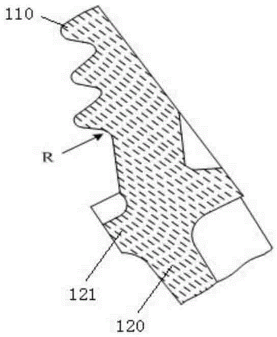
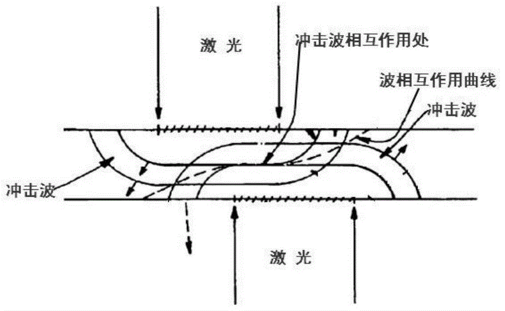
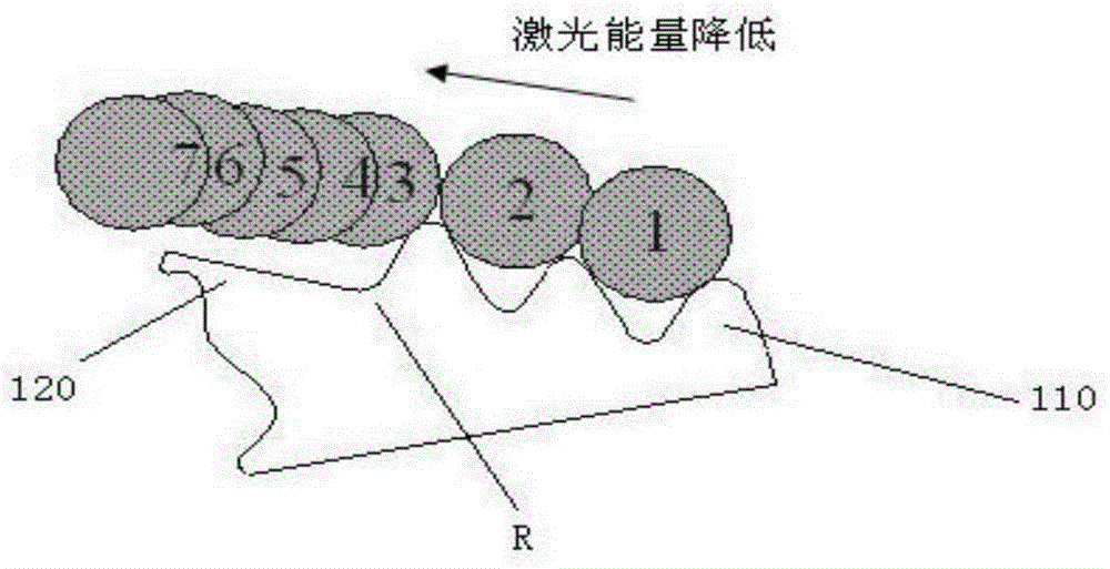
A laser shock strengthening and turbine rotor technology, applied in the aviation field, can solve the problems of short service life and crack fracture, and achieve the effect of avoiding fatigue fracture, prolonging service life and improving fatigue performance.
- Summary
- Abstract
- Description
- Claims
- Application Information
AI Technical Summary
Problems solved by technology
Method used
Image
Examples
Embodiment 1
[0044] 1) Inspect and clean the turbine blades that need to be strengthened;
[0045] 2) The laser enters the preparation stage, adjust the corresponding parameters in the laser, the laser shock strengthening parameters are: laser wavelength 1064nm, laser pulse frequency 1Hz, laser pulse waveform width 22nm, focus spot size before laser projection ∮3.2mm. On the corresponding area of the surface of the blade to be treated, water is used to form a constrained layer, the thickness of the formed constrained layer is 5 mm, and the water pressure is 0.04 MPa. Laser power density 7.96GW / cm 2 , the overlap rate is 100%.
[0046] 3) Paste the absorbing protective layer on the surface of the blade to be treated, and use aluminum foil as the absorbing protective layer;
[0047] 4) The blade is clamped on the laser, and the position to be treated is positioned, and then impact strengthening is performed on the blade according to the above conditions. During processing, the laser ene...
Embodiment 2
[0051] 1) Inspect and clean the turbine blades that need to be strengthened;
[0052] 2) The laser enters the preparation stage, adjust the corresponding parameters in the laser, the laser shock strengthening parameters are: laser wavelength 1064nm, laser pulse frequency 1Hz, laser pulse waveform width 18nm, focus spot size before laser projection ∮ 2.8mm. On the corresponding area of the surface of the blade to be treated, water is used to form a constrained layer, the thickness of the formed constrained layer is 0.5 mm, and the water pressure is 0.04 MPa. Laser power density 3.3GW / cm 2 , The overlapping rate is 65%.
[0053] 3) paste the absorbing protective layer on the surface of the blade to be treated, and use black paint as the absorbing protective layer;
[0054] 4) The blade is clamped on the laser, and the position to be treated is positioned, and then impact strengthening is performed on the blade according to the above conditions. During processing, the laser ...
Embodiment 3
[0058] 1) Inspect and clean the turbine blades that need to be strengthened;
[0059] 2) The laser enters the preparation stage, and adjusts the corresponding parameters in the laser. The laser shock strengthening parameters are: laser wavelength 1064nm, laser pulse frequency 1Hz, laser pulse waveform width 20nm, laser focus spot size ∮3mm before projection. On the corresponding area of the surface of the blade to be treated, water is used to form a constrained layer, the thickness of the formed constrained layer is 1 mm, and the water pressure is 0.04 MPa. Laser power density 4.3GW / cm 2 , the overlap rate is 100%.
[0060] 3) paste the absorbing protective layer on the surface of the blade to be treated, and use the adhesive tape as the absorbing protective layer;
[0061] 4) The blade is clamped on the laser, and the position to be treated is positioned, and then impact strengthening is performed on the blade according to the above conditions. During processing, the las...
PUM
| Property | Measurement | Unit |
|---|---|---|
| Overlap rate | aaaaa | aaaaa |
| Overlap rate | aaaaa | aaaaa |
Abstract
Description
Claims
Application Information
 - R&D
- Intellectual Property
- Life Sciences
- Materials
- Tech Scout
- Unparalleled Data Quality
- Higher Quality Content
- 60% Fewer Hallucinations
Browse by: Latest US Patents, China's latest patents, Technical Efficacy Thesaurus, Application Domain, Technology Topic, Popular Technical Reports.
© 2025 PatSnap. All rights reserved.Legal|Privacy policy|Modern Slavery Act Transparency Statement|Sitemap|About US| Contact US: help@patsnap.com


