
Logistic vehicle control system based on visible light positioning and navigation

A control system and logistics vehicle technology, applied in the field of positioning and control, can solve the problems of inapplicability, high technical requirements of the method, scattering and reflection of ultrasonic waves, etc., and achieve the effects of automation and intelligence, low cost and convenient transplantation

Active Publication Date: 2015-10-07
上海楚伟自动化科技有限公司
View PDF7 Cites 16 Cited by
  • Summary
  • Abstract
  • Description
  • Claims
  • Application Information

AI Technical Summary

Problems solved by technology

The positioning methods based on WiFi and cellular networks are limited by the low penetration of satellite signals, channel noise and multipath interference, which greatly affect the accuracy of outdoor positioning and are not suitable for accurate indoor positioning.
ZigBee and RFID positioning methods can avoid the problem of weak indoor signal of satellite positioning to a certain extent, but the technical requirements of the method are relatively high, and the positioning effect is greatly affected by the indoor layout, so this method is not suitable for many occasions such as warehouses and supermarkets. Be applicable
Due to the two characteristics of infrared line-of-sight and low transmission distance, infrared positioning method is very effective in the occasions with simple indoor structure and limited indoor area. Therefore, this method is not practical
The ultrasonic positioning method requires a large amount of underlying hardware investment in the initial stage, and the ultrasonic wave will be affected by scattering and reflection during transmission, so it is not suitable for supermarkets, airports and other public places

Method used


Image

  • Logistic vehicle control system based on visible light positioning and navigation
  • Logistic vehicle control system based on visible light positioning and navigation
  • Logistic vehicle control system based on visible light positioning and navigation

Examples


Embodiment Construction

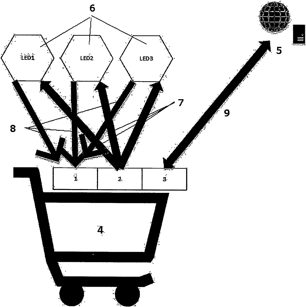
[0011] figure 1 The main components of the system are introduced: CCD camera (1), infrared transmitter (2), motion control module (3) as the three main modules on the logistics vehicle (4). The infrared emitter (2) continuously transmits an infrared clock synchronization signal (7), and when the LED visible light positioning mark (6) receives the synchronization signal, it transmits an LED data signal (8) with a signal according to a determined unique encoding method. After the CCD camera receives the LED data signal (8), it decodes to obtain the serial number of the LED positioning mark (6), and calculates the distance from the LED signal emission point through the light intensity. Through RSSI's triangular positioning method, the precise location information of the logistics vehicle can be obtained after knowing the numbers of the three LED signs and the distance to them. After the logistics vehicle obtains the location, it communicates with the server through a wireless co...


PUM


Abstract

Provided is a logistic vehicle control system based on visible light positioning and navigation. The logistic vehicle control system comprises a CCD camera, an infrared emitter, a motion control module, an LED positioning marker, and a server and a correlative communication network for system control, wherein the CCD camera, the infrared emitter, and the motion control module are installed on a logistic vehicle. The logistic vehicle control system acquires a unique response data signal of the LED positioning marker by means of an infrared synchronizing signal emitted from the infrared emitter on the logistic vehicle, acquires the information of the marker by decoding, measures distance to the marker by light intensity, acquires the accurate positional information of the logistic vehicle by using a RSSI triangular positioning method, uploads the positional information to the server in real time, and acquires a motion control instruction given by the server to achieve intelligent control. The logistic vehicle control system uses a visible light positioning manner, prevents multiple limitation of other indoor positioning manners, and is high in precision, simple in structure, easy to produce, and beneficial to intelligent control of logistic vehicles in factories and warehouses.

Description

technical field [0001] The invention belongs to the technical field of positioning and control, and in particular relates to a control system that uses visible light to locate logistics vehicles and uses wireless control technology to navigate. Background technique [0002] In factories, warehouses, supermarkets, storage rooms and other places, logistics vehicles have become an important tool for storage and transportation of goods. With the development of science and technology, highly intelligent automatic warehouse control system has gradually attracted people's attention. Highly automated logistics vehicles and a set of navigation systems with good control performance are necessary to realize the intelligence and automation of warehousing and transportation. Among them, the accurate positioning of logistics vehicles is an important guarantee for the good controllability of the system. Considering that it is mostly used in indoor situations in practical applications, log...

Claims


Application Information

Patent Timeline
IPC IPC(8): G05D1/02G01S5/16G01S11/12
Inventor 倪欢周庆杲
Owner 上海楚伟自动化科技有限公司
Learn More