
Fiber Cooling Unit

A cooling device and optical fiber technology, applied in glass manufacturing equipment, manufacturing tools, etc., can solve the problems of inert gas rapid distribution uniformity, production trouble, contact and other problems, and achieve a concise overall structure, which is conducive to production and assembly Effect

Active Publication Date: 2017-04-12
QINGHAI ZHONGLI OPTICAL FIBER TECH CO LTD
View PDF5 Cites 0 Cited by
  • Summary
  • Abstract
  • Description
  • Claims
  • Application Information

AI Technical Summary

Problems solved by technology

This patent solution can objectively embody the technical effect described in paragraph 0010 of its description, but it has the following shortcomings: First, due to the need to fit a cylindrical baffle on the inner wall of the coil and distribute small holes on the cylindrical baffle, Therefore, the actual production is more troublesome; second, due to the fact that the optical fiber cooling device needs to be installed in the aforementioned furnace mouth and winding station, furnace mouth and extrusion coating station or the furnace mouth and optical fiber surface coloring in the actual use state Therefore, the convenience of actual installation is an important factor that cannot be neglected, and the patent scheme does not give corresponding enlightenment; thirdly, since the inert gas inlet is set in the cylindrical pipe body up to four meters The middle part is set at half of the length direction of the cylindrical tube body and the inert gas introduced by it needs to enter the baffle cavity through the small hole on the cylindrical baffle, so for the cylindrical tube body, The rapid distribution uniformity of the inert gas is objectively affected to a certain extent, and the optical fiber passing through the baffle cavity is still in danger of contacting the oxidizing gas

Method used


Image

  • Fiber Cooling Unit
  • Fiber Cooling Unit
  • Fiber Cooling Unit

Examples


Embodiment Construction

[0021] In order to enable the examiners of the patent office, especially the public, to understand the technical essence and beneficial effects of the present invention more clearly, the applicant will describe in detail the following in the form of examples, but none of the descriptions to the examples is an explanation of the solutions of the present invention. Any equivalent transformation made according to the concept of the present invention which is merely formal but not substantive shall be regarded as the scope of the technical solution of the present invention.

[0022] In the following descriptions, all concepts involving up, down, left, right, front and rear directionality (or orientation) are for the position state of the picture being described, and the purpose is to facilitate the public Therefore, it cannot be understood as a special limitation on the technical solution provided by the present invention.

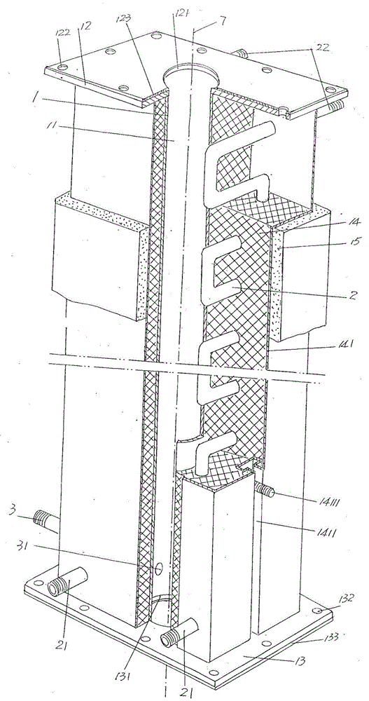
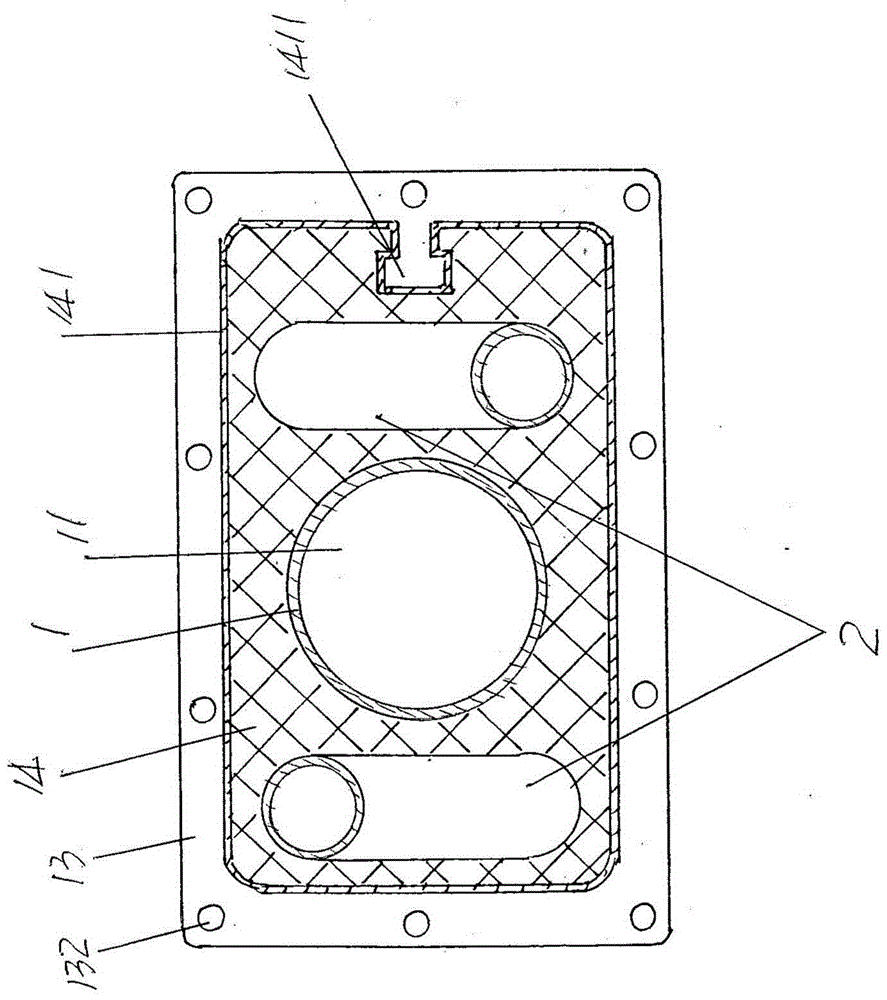
[0023] See figure 1 , a cooling pipe 1 of the structura...


PUM


Abstract

An optical fiber cooling device belongs to the technical field of supporting auxiliary facilities for optical fiber production. Including the cooling pipe, the upper flange connecting plate is fixed on the top, the lower flange connecting plate is fixed on the bottom, the outer wall is covered with a temperature-conducting layer, the outer surface of the temperature-conducting layer is covered by a temperature-conducting layer sealing plate, and the temperature-conducting layer The middle position on the right side of the sealing plate forms a T-shaped screw groove, and T-shaped screws are arranged on the T-shaped screw groove; a pair of medium cooling pipes, one of which is laid in the temperature conducting layer corresponding to the left side of the cooling pipe, The other is laid in the temperature-conducting layer corresponding to the right side of the cooling pipe; the inert gas is introduced into the connecting pipe, one end of which is fixed to the cooling pipe, and the other end protrudes from the temperature-conducting layer and is connected to the inert gas supply source. Conducive to manufacture and assembly; it is convenient to install the invention between the furnace mouth and the winding station, the furnace mouth and the optical fiber outer extrusion station, or the furnace mouth and the optical fiber surface coloring station; it makes the optical fiber cool down quickly and evenly ; Contribute to the rapid diffusion of inert gas in the cooling tube cavity to ensure the quality.

Description

technical field [0001] The invention belongs to the technical field of supporting auxiliary facilities for optical fiber production, and in particular relates to an optical fiber cooling device. Background technique [0002] Since the optical fiber is obtained by drawing the optical fiber preform (also called quartz glass rod), the optical fiber still reaches a high temperature of about 1000°C when it comes out of the furnace, that is, after the optical fiber is formed, so in the limited interval from the furnace mouth to the winding station ( Refers to the drawing process) or the limited section that is extruded from the furnace mouth to the outside (referring to the optical fiber production process) is not enough to reduce the temperature of the optical fiber from about 1000 ° C to the level that tends to be similar to the ambient temperature by natural cooling, so that the coil Winding or extruding the outer jacket and even coloring the surface of the optical fiber will h...

Claims


Application Information

Patent Timeline
Patent Type & Authority Patents(China)
IPC IPC(8): C03B37/01
Inventor 赵海林袁积鸿王翔刘发燕盛小萍
Owner QINGHAI ZHONGLI OPTICAL FIBER TECH CO LTD
Learn More