Catalytic cracking method of increasing gasoline yield

A catalytic cracking and gasoline technology, applied in the field of catalytic cracking, can solve the problem of limited increase in gasoline yield, achieve the effect of reducing the amount of catalytic diesel, lowering the contact temperature of oil agent, and reducing the yield of dry gas and coke

Active Publication Date: 2015-10-14
LUOYANG PETROCHEMICAL ENG CORP SINOPEC +1
View PDF6 Cites 0 Cited by
  • Summary
  • Abstract
  • Description
  • Claims
  • Application Information

AI Technical Summary

Problems solved by technology

[0008] It can be seen from the analysis that the above process methods mainly increase the gasoline yield by increasing the ratio of agent to oil. Although the increase of gasoline yield can be realized to a certain extent, the increase in gasoline yield is very limited.

Method used


Image

  • Catalytic cracking method of increasing gasoline yield
  • Catalytic cracking method of increasing gasoline yield
  • Catalytic cracking method of increasing gasoline yield

Examples


Embodiment 1

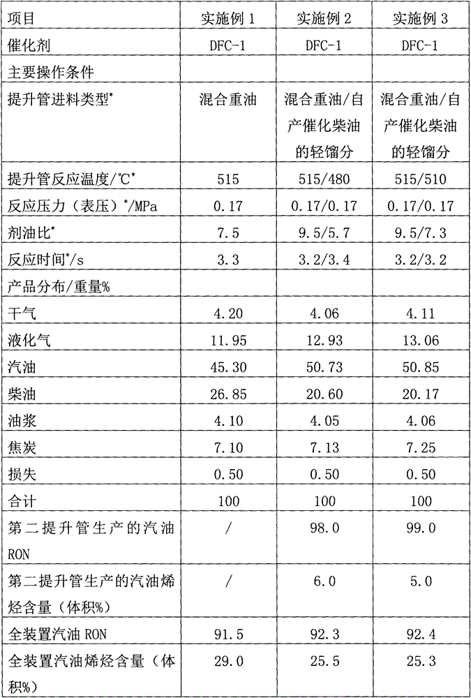
[0027] Example 1 (comparative example)

[0028] The test was carried out on a conventional single riser catalytic cracking test device. The feed of the riser was mixed heavy oil, the main properties are listed in Table 1, and the processing capacity was 30 kg / day; the catalyst used in the test was DFC-1 industrial balancer, and the balance catalyst was micro The reaction activity is 65, and the carbon content is 0.03w%. The main operating conditions, product distribution and main properties of gasoline are shown in Table 2.

Embodiment 2

[0030] The test was carried out on a double riser catalytic cracking test device. The feed of the first riser was the mixed heavy oil of Example 1, and the processing capacity was 30 kg / day; the feed of the second riser was the light fraction of all the catalytic diesel produced by the device. The processing capacity is 15 kg / day. The catalyst used in the test is the DFC-1 industrial balancer, the balance catalyst has a micro-reactive activity of 65 and a carbon content of 0.03w%. The main operating conditions, product distribution and main properties of gasoline of the dual riser catalytic cracking test device are listed in Table 2.

Embodiment 3

[0032] According to Example 2, the difference is that the reaction temperature of the second riser is 510°C. The main operating conditions, product distribution and main properties of gasoline are listed in Table 2.


PUM


Abstract

The invention discloses a catalytic cracking method of increasing gasoline yield, which comprises the following steps: (A) feeding raw material oil to the lower part of a first lifting tube reactor and carrying out a contact reaction to the raw material oil with a catalyst from a pre-lifting mixer; (B) feeding a to-be-regenerated catalyst from the first lifting tube reactor into a steam stripping part of a main precipitator, performing steam stripping and regenerating the catalyst in a regenerator; (C) feeding catalytic diesel or hydrotreated catalytic diesel into the lower part of a second lifting tube reactor and carrying out a contact reaction with the catalyst from the regenerator; (D) feeding the to-be-regenerated catalyst from the second lifting tube reactor into a steam stripping part of a sub precipitator; (E) performing air stripping to the to-be-regenerated catalyst from the steam stripping part of the sub precipitator, feeding one part of the catalyst into the regenerator and regenerating the catalyst, and feeding the other one part of the catalyst into the pre-lifting mixer and mixing the catalyst with the regenerated catalyst from the regenerator; and (F) feeding the mixed catalyst into the lower part of the first lifting tube reactor and carrying out a contact reaction with the raw material oil. By means of the method, the catalytic cracking device is increased by 3-20% in gasoline yield, is increased by more than 0.5 units in RON of gasoline and is reduced in the content of olefin by more than 3% by volume. The gasoline directly produced in the second lifting tube reactor is higher than 96 in RON and is less than 10% in the content of olefin.

Description

Technical field [0001] The present invention belongs to the field of catalytic cracking of hydrocarbon oil in the absence of hydrogen, and particularly relates to a catalytic cracking method for producing more gasoline. Background technique [0002] Catalytic cracking unit is an important secondary processing unit in the oil refining industry, as well as the main processing unit for the production of automotive gasoline. At present, more than 65% of the domestic automotive gasoline blending components are catalytically cracked gasoline. Gasoline olefin content requirements and strong market demand for propylene have given rise to various catalytic cracking processes that reduce gasoline olefin content and increase propylene production. However, while achieving these goals, the gasoline yield of catalytic cracking units has gradually reduce. [0003] With the enrichment of domestic oil refining and processing methods and the changes in market demand, on the one hand, the proportion...

Claims


Application Information

Patent Timeline
IPC IPC(8): C10G55/06
Inventor 闫鸿飞孟凡东张亚西王龙延李秋芝武立宪
Owner LUOYANG PETROCHEMICAL ENG CORP SINOPEC
Why Eureka
Try Eureka