Semiconductor device, diagnostic test, and diagnostic test circuit

A diagnostic test and semiconductor technology, which is applied in the field of diagnosis of multiple CPU cores, can solve problems such as operational performance deterioration, and achieve the effect of preventing deterioration

Active Publication Date: 2015-10-14
RENESAS ELECTRONICS CORP
View PDF14 Cites 11 Cited by
  • Summary
  • Abstract
  • Description
  • Claims
  • Application Information

AI Technical Summary

Problems solved by technology

In the technique disclosed in Japanese Unexamined Patent Application Publication No. H10-11319, since the boundary scan test is performed by using a scan chain extending through all CPU boards, it is impossible to operate any CPU board when the boundary scan timeout is performed, thus causing The problem of poor operating performance

Method used


Image

  • Semiconductor device, diagnostic test, and diagnostic test circuit
  • Semiconductor device, diagnostic test, and diagnostic test circuit
  • Semiconductor device, diagnostic test, and diagnostic test circuit

Examples


no. 1 example

[0046] First, the configuration and operation according to the first embodiment will be described with reference to the drawings.

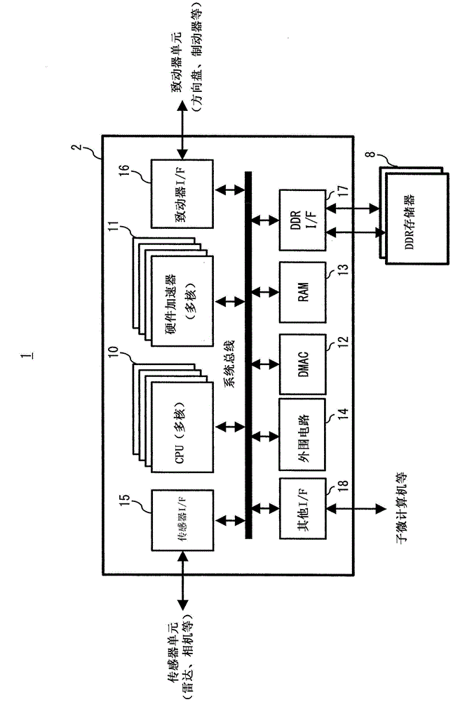
[0047] figure 1 is a block diagram showing an example of a configuration of a CPU system 2 for an ADAS (Advanced Driver Assistance System) of an in-vehicle ECU (Electronic Control Unit) 1 that requires high operational performance. The on-vehicle ECU 1 includes a CPU system (main microcomputer) 2 and a plurality of DDR (Double Data Rate) memories 8 as external memories. The CPU system 2 includes an internal processing circuit, a CPU (multi-core) 10 with a multi-core architecture, a hardware accelerator (multi-core) 11 with a multi-core architecture, a DMAC (Direct Memory Access Controller) 12, a RAM (Random Access Memory) 13, and others Peripheral Circuitry 14. Also, the CPU system 2 includes a sensor I / F 15 , an actuator I / F 16 , a DDR I / F 17 , and other I / F 18 as circuits for external interfaces.

[0048] These circuits 10 to 18 are connected...

no. 2 example

[0109] Next, the configuration and operation according to the second embodiment will be described with reference to the drawings.

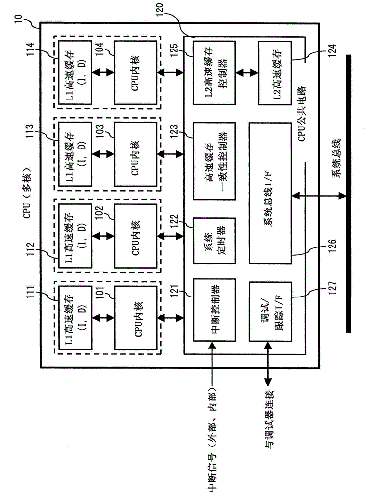
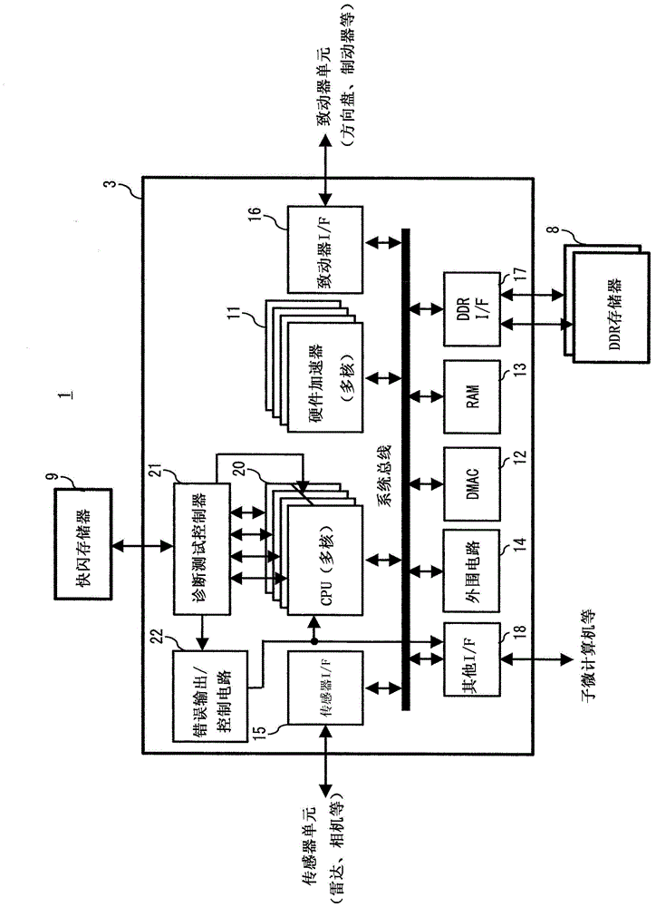
[0110] The configuration and operations of the second embodiment are basically similar to those of the first embodiment. That is, the components of the second embodiment are the same as those in image 3 Basically similar to those in the CPU system 3 shown in the CPU system 3 included in Figure 4 The CPU shown in 20 and the Figure 5 The CPU core 101 (each of the CPU cores 102 to 104 is similar to the CPU core 101 ) and the scan test circuit 201 (each of the scan test circuits 202 to 204 is similar to the scan test circuit 201 ) are shown in . Also, execution of diagnostic tests for the CPU cores 101 to 104 according to the second embodiment is also similar to that in Figure 6 and 7 Execution of the diagnostic tests for the CPU core shown in .

[0111] However, the input test pattern for the scan test input to the CPU cores 101 to 104 has 8...

no. 3 example

[0125] Next, the configuration and operation according to the third embodiment will be described with reference to the drawings.

[0126] Figure 14 is a block diagram showing the configuration of the CPU system 4 according to the third embodiment. with in image 3 The CPU system 3 according to the first embodiment shown in is different in that the CPU system 4 additionally includes a startup time test circuit 24 that performs a diagnostic test for a diagnostic test controller 25 when the system is started.

[0127] When the CPU system 4 is started, the startup time test circuit 24 executes a diagnostic test for the diagnostic test controller 25 before the diagnostic test controller 25 starts execution of the diagnostic test for the CPU cores 101 to 104 . Note that the diagnostic test controller 25 according to the third embodiment is obtained by adding a circuit for performing a diagnostic test for the diagnostic test controller 25 in the diagnostic test controller 21 . De...


PUM


Abstract

Deterioration in operation performance due to a fault diagnosis is prevented. A semiconductor device (90) according to the present invention includes a plurality of CPU cores (91 to 94) each including a scan chain, and a diagnostic test circuit (95) that performs a scan test for the plurality of CPU cores (91 to 94) by using the scan chain of the CPU core. The diagnostic test circuit (95) performs a scan test for each of the plurality of CPU cores (91 to 94) in a predetermined order on a periodic basis so that execution time periods of the scan tests do not overlap each other.

Description

technical field [0001] The present invention relates to semiconductor devices, diagnostic tests and diagnostic test circuits in semiconductor devices. For example, the present invention can be suitably used for diagnosis of a plurality of CPU cores. Background technique [0002] In order to achieve high computing performance, a CPU (Central Processing Unit) system with a multi-core architecture is desired. However, if a fault occurs in one of the CPU cores, this fault needs to be detected immediately and the system brought into a safe state with regard to functional safety. However, use of a program (software) that performs self-diagnosis based on an instruction set for performing fault diagnosis of a high-performance CPU cannot provide satisfactory results in both fault detection rate (diagnosis coverage) and diagnosis time (program execution time) . For example, even if a self-diagnostic program can be built that can achieve high diagnostic coverage, it is certain that ...

Claims


Application Information

Patent Timeline
Patent Type & Authority Applications(China)
IPC IPC(8): G01R31/28
CPCG01R31/3177G01R31/318544G06F11/08
Inventor 坪井幸利长野英生长冈浩司松永祐介井学丰久保田尚孝
Owner RENESAS ELECTRONICS CORP
Why Eureka
Try Eureka