Minitype solid rocket engine structure based on 3D printing technology

A solid rocket and 3D printing technology, applied in the direction of rocket engine devices, machines/engines, mechanical equipment, etc., can solve the problems of small nozzle size, difficult installation, poor aerodynamic characteristics, etc., to achieve stable aerodynamic parameters, short process cycle, The effect of simple structure

Inactive Publication Date: 2015-10-21
NORTHWESTERN POLYTECHNICAL UNIV
View PDF4 Cites 8 Cited by
  • Summary
  • Abstract
  • Description
  • Claims
  • Application Information

AI Technical Summary

Problems solved by technology

[0004] 1. Vapor tends to condense or solidify in the propellant lines or at the nozzle
[0005] 2. There is a more complicated micro-pipeline system, which reduces the reliability of the system
[0007] 1. The size of the nozzle is small, and it must be divided into 3 layers, the structure is complex, and the process requirements are high
[0008] 2. The igniter is installed in the throat, which is difficult to install; the lead wire of the ignition resistance wire is difficult to lead out
[0009] 3. The diameter of the throat of the micro engine is small, and the alignment and bonding of the top plate and the middle plate are difficult
[0011] 1. The nozzle manufactured by the MEMS process is square and has poor aerodynamic characteristics
[0012] 2. The igniter can only be installed on the front head
[0013] 3. When the nozzle layer and the combustion chamber layer are charged and bonded, the charge inside the combustion chamber layer may explode, which is poor in safety

Method used


Image

  • Minitype solid rocket engine structure based on 3D printing technology
  • Minitype solid rocket engine structure based on 3D printing technology

Examples


Embodiment Construction

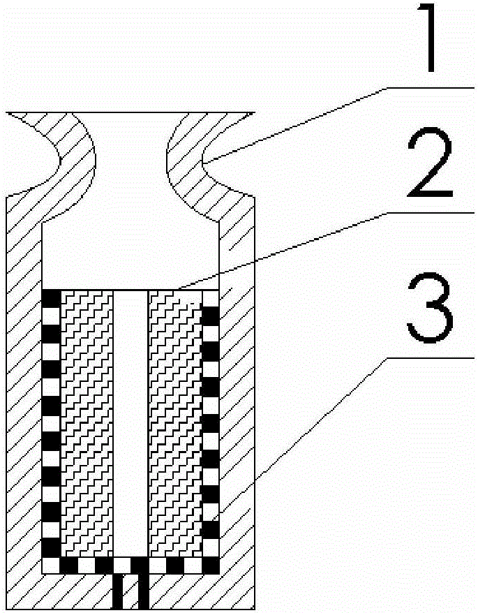
[0028] This embodiment is a miniature solid rocket motor structure based on 3D printing technology.

[0029] Different from the traditional micro-engine front head, combustion chamber, nozzle and powder column, which are processed separately and then assembled, all the parts in this embodiment are printed together, which is an airtight entity. According to the different materials used, the structure of the miniature solid rocket motor designed in this embodiment consists of three parts: the casing 1, the metal igniter 3 and the grain 2. The casing 1 includes a combustion chamber, a nozzle, and a front head, all of which are made of silicon material; the nozzle has a converging section and an expanding section; the metal igniter 3 is made of a copper conductor metal material; the powder column 2 is any solid The propellant; the casing 1, the metal igniter 3 and the powder column 2 form an integral structure.

[0030] The working principle of the miniature solid rocket motor: t...


PUM


Abstract

The invention discloses a minitype solid rocket engine structure based on a 3D (Three Dimensional) printing technology, which comprises a three-spray-head printer, wherein the printer prints different materials of a design entity in each cross section, and prints a housing, an explosive column and a metal igniter into an integrated structure; the housing consists of a combustion chamber, a spray pipe and a front end socket; the spray pipe is provided with a convergent section and an expansion section; the metal igniter is positioned on the inner surface of the combustion chamber; a lead wire of the metal igniter is led out from the front end socket, and connected with a control chip in an independently addressing manner; different quantities of metal igniters are triggered, and directly ignite the explosive columns in the combustion chambers; the metal igniters are made of copper materials; and the explosive columns are made of any one of solid propellant materials. The minitype solid rocket engine structure is easy to ignite, reliable in sealing, and simple; a total impulse is higher; a minitype engine array is formed by printing multiple minitype engines which are in the same size and are arranged and distributed at equal intervals; the operation is concise; and a technology cycle is short.

Description

technical field [0001] The invention belongs to the field of micro solid rocket motor structure design, in particular, relates to a micro solid rocket motor structure based on 3D printing technology. Background technique [0002] The miniature solid rocket motor attached to the miniature spacecraft needs to be able to perform high-precision site tracking, attitude control, gravity compensation, and orbit adjustment, and traditional miniature engines cannot meet the required thrust accuracy and space requirements. In the past few decades, micro-engine technology has been a hot research field, and among the numerous research projects, the feasibility of downsizing traditional micro-engines has been studied. Several micro-engine technologies have been developed, such as: micro-electric propulsion technology, micro-cooled air propulsion technology, micro-laser plasma propulsion technology, which can provide 10 -8 Thrust pulses of N·s~10N·s can provide precise control for spacec...

Claims


Application Information

Patent Timeline
Patent Type & Authority Applications(China)
IPC IPC(8): F02K9/08
Inventor 胡松启吴晶辉武冠峰李进贤刘茜
Owner NORTHWESTERN POLYTECHNICAL UNIV
Why Eureka
Try Eureka