Magnetic field measurement method based on surface plasma resonance technology

A surface plasmon and magnetic field measurement technology, which is applied in the magnetic field measurement, magnetic field size/direction and other directions using magneto-optical equipment, can solve the problem of low effective refractive index, achieve high sensitivity measurement, and reduce complexity.

Inactive Publication Date: 2015-10-21
NORTHEASTERN UNIV
View PDF5 Cites 3 Cited by
  • Summary
  • Abstract
  • Description
  • Claims
  • Application Information

AI Technical Summary

Problems solved by technology

[0005] The purpose of the present invention is to solve the problem that the effective refractive index changes with the magnetic field is low when the "two-phase separat

Method used


Image

  • Magnetic field measurement method based on surface plasma resonance technology
  • Magnetic field measurement method based on surface plasma resonance technology
  • Magnetic field measurement method based on surface plasma resonance technology

Examples


Embodiment Construction

[0020] In order to make the purpose, technical solution and advantages of the present invention more clear, the specific structure, principle and performance optimization process of the present invention will be further described in detail below in conjunction with specific embodiments and with reference to the accompanying drawings.

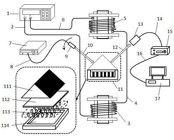
[0021] figure 1 It is a schematic diagram of the magnetic field measurement system of the prism coupling combined with the magnetic fluid provided by the present invention. The light emitted by the light source enters the collimator through the optical fiber to form a spatial optical path, and the reflected light after passing through the sensing unit receives the signal through the photodetector, and then enters the computer system for signal acquisition, processing and display after passing through the processing circuit. The uniform magnetic field generated by the coil connected with the DC power acts on the magnetic fluid in the sensing unit...


PUM

PropertyMeasurementUnit
Thicknessaaaaaaaaaa

Abstract

The invention provides a magnetic field measurement method based on the surface plasma resonance technology, comprising a DC source 1, a copper coil 3, a copper coil 5, a light source 7, a sensing probe 11, a processing circuit 15 and a computer system 17, and characterized by employing a magnetofluid 113 and a gold film 112 to take effect mutually to realize surface plasma resonance. A glass groove 114 is filled with the magnetofluid 113, and upper and lower surfaces are provided with magnetic fields to change resonance angles; and then the intensities of the magnetic fields are changed to change a magnetofluid microstructure to furthermore modulate surface plasma waves. The method can reduce the influence caused by medium loss, and realize magnetic field measurement of 0.0173deg/Oe and 0.054deg/Oe sensitivities respectively in a low magnetic field cope and a high magnetic field scope.

Description

technical field [0001] The invention relates to a magnetic field measurement method based on surface plasmon resonance technology, and belongs to the technical field of micro-optoelectronic detection. Background technique [0002] Optical fiber sensing technology is based on optical principles for measurement, and has the advantages of non-contact and non-destructive measurement, almost no interference, high-speed transmission, and telemetry. After decades of development, it has become a research hotspot all over the world ( Literature 1. Hou Junfang, Pei Li, Li Zhuoxuan and Liu Chao’s research progress and application of optical fiber sensing technology [J], Optoelectronics Technology Application, 2012, 27 (1): 49-53), based on these advantages, researchers proposed a method based on Magnetic field devices for measuring optical effects such as Faraday effect and Fresnel reflection, but these methods have problems such as low measurement sensitivity and the large absorption ...

Claims


Application Information

Patent Timeline
IPC IPC(8): G01R33/032
Inventor 赵勇英宇
Owner NORTHEASTERN UNIV
Why Eureka
Try Eureka