Filter parameter optimization method based on visible light communication

A technology of visible light communication and optimization method is applied in the field of optimization of filter parameters in polychromatic light communication system to achieve the effect of reducing cross-interference

Active Publication Date: 2015-10-21
SOUTHEAST UNIV
View PDF4 Cites 10 Cited by
  • Summary
  • Abstract
  • Description
  • Claims
  • Application Information

AI Technical Summary

Problems solved by technology
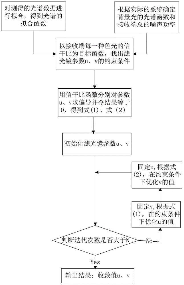
However, there is no relevant research on how to

Method used


Image

  • Filter parameter optimization method based on visible light communication
  • Filter parameter optimization method based on visible light communication
  • Filter parameter optimization method based on visible light communication

Examples


Embodiment 1

[0081] Embodiment 1: pass band characteristic is the optical filter of rectangle

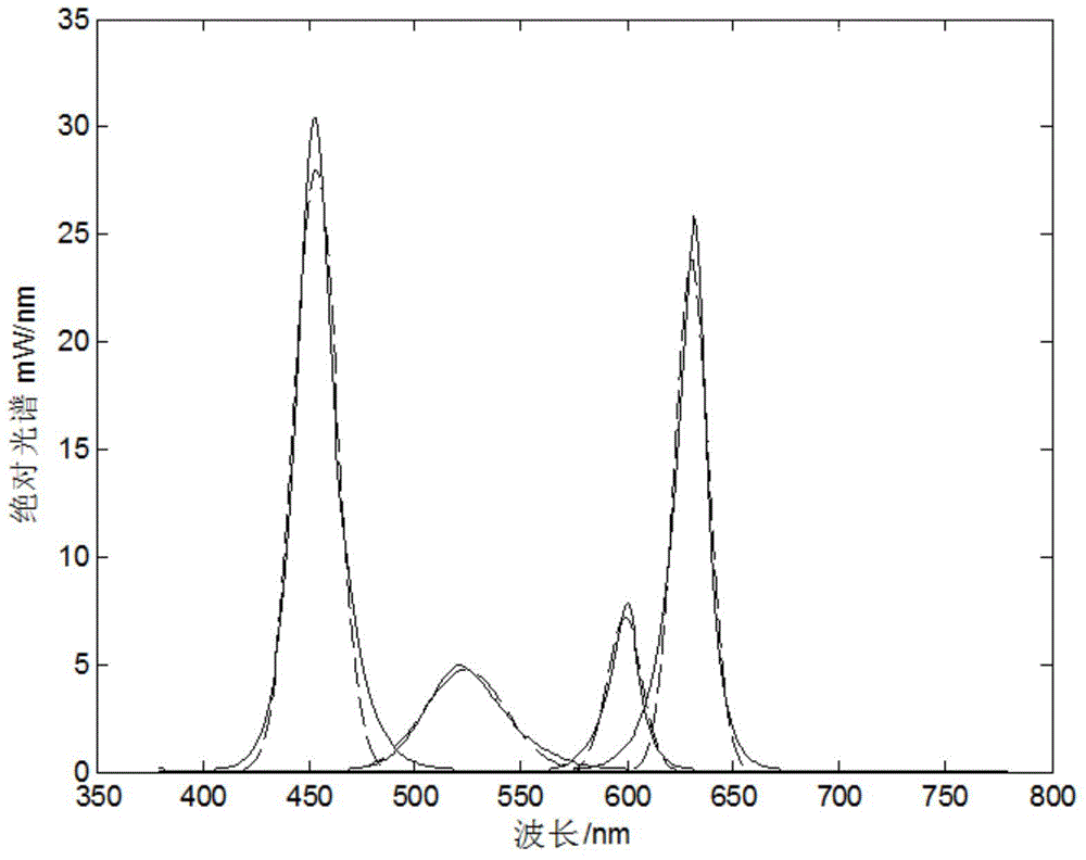
[0082] (1) The expression for fitting the four-color light source with a Gaussian function is as follows:

[0083] S r (λ)=a 1 exp[-(λ-λ 1 ) 2 / σ 1 2 ]

[0084] S a (λ)=a 2 exp[-(λ-λ 2 ) 2 / σ 2 2 ]

[0085] S g (λ)=a 3 exp[-(λ-λ 3 ) 2 / σ 3 2 ]

[0086] S b (λ)=a 4 exp[-(λ-λ 4 ) 2 / σ 4 2 ]

[0087] The result obtained with the matlab fitting tool is:

[0088] S r(λ)=23.86exp[-(λ-630.5) 2 / 11.6 2 ]

[0089] S a (λ)=7.177exp[-(λ-599) 2 / 11.6 2 ]

[0090] S g (λ)=4.734exp[-(λ-523.7) 2 / 27.38 2 ]

[0091] S b (λ)=28exp[-(λ-453.3) 2 / 14.3 2 ]

[0092] (2) The spectral function of the background light (here it is assumed that the spectral amplitude of the background light is uniform):

[0093] Take S respectively back (λ)=P=0 and S back (λ)=P=0.5mW / nm

[0094] Total noise power at the receiving end (including shot noise, thermal noise, etc.): N t =10mW

...

Embodiment 2

[0118] Embodiment 2: the passband characteristic is the optical filter of Gauss

[0119] (1) The expression for fitting the four-color light source with a Gaussian function is as follows:

[0120] S r (λ)=a 1 exp[-(λ-λ 1 ) 2 / σ 1 2 ]

[0121] S a (λ)=a 2 exp[-(λ-λ 2 ) 2 / σ 2 2 ]

[0122] S g (λ)=a 3 exp[-(λ-λ 3 ) 2 / σ 3 2 ]

[0123] S b (λ)=a 4 exp[-(λ-λ 4 ) 2 / σ 4 2 ]

[0124] The result obtained with the matlab fitting tool is:

[0125] S r (λ)=23.86exp[-(λ-630.5) 2 / 11.6 2 ]

[0126] S a (λ)=7.177exp[-(λ-599) 2 / 11.6 2 ]

[0127] S g (λ)=4.734exp[-(λ-523.7) 2 / 27.38 2 ]

[0128] S b (λ)=28exp[-(λ-453.3) 2 / 14.3 2 ]

[0129] (2) The spectral function of the background light (here it is assumed that the spectral amplitude of the background light is uniform):

[0130] Take S respectively back (λ)=P=0 and S back (λ)=P=0.5mW / nm

[0131] Total noise power at the receiving end (including shot noise, thermal noise, etc.): N t =10mW

...

Embodiment 3

[0160] Example 3: Filters whose passband characteristics are Lorentzian

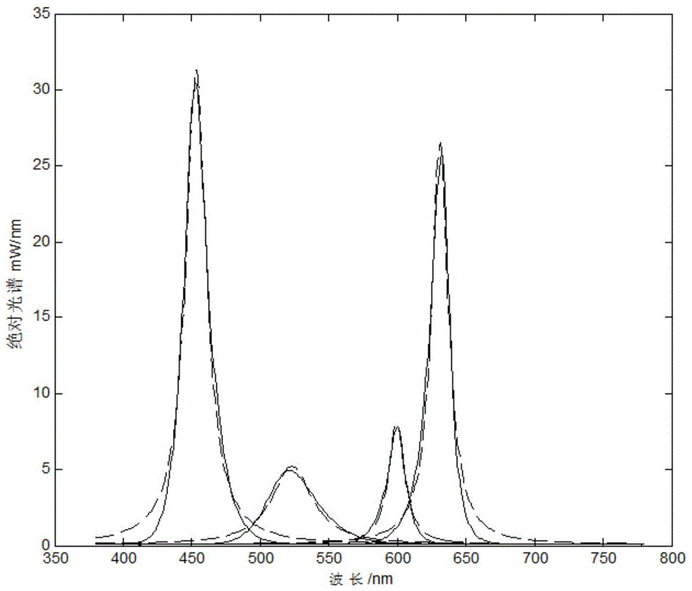
[0161] (1) The expression of the four-color light source fitted by the Lorentz function is as follows:

[0162] (For the convenience of derivation and calculation, the light source spectrum is fitted with the Lorentz function here, which is acceptable within the allowable range of error.)

[0163] S r (λ)=a 1 / (1+(λ-λ 1 ) 2 / σ 1 2 )

[0164] S a (λ)=a 2 / (1+(λ-λ 2 ) 2 / σ 2 2 )

[0165] S g (λ)=a 3 / (1+(λ-λ 3 ) 2 / σ 3 2 )

[0166] S b (λ)=a 4 / (1+(λ-λ 4 ) 2 / σ 4 2 )

[0167] The result obtained with the matlab fitting tool is:

[0168] S r (λ)=26.56 / (1+(λ-630.9) 2 / 7.507 2 )

[0169] S a (λ)=8.033 / (1+(λ-599.2) 2 / 7.135 2 )

[0170] S g (λ)=5.214 / (1+(λ-523.1) 2 / 17.82 2 )

[0171] S b (λ)=31.36 / (1+(λ-453.1) 2 / 9.132 2 )

[0172] (2) The spectral function of the background light (here it is assumed that the spectral amplitude of the background light is uniform): ...


PUM


Abstract

The invention provides a filter parameter optimization method based on visible light communication, comprising: firstly utilizing a spectrometer to detect the spectrum data of each monochromatic light, and employing a gauss or Lorentzen function for fitting to obtain a spectral fitting function; in dependence on a real system, determining the spectral function of a bias light and the total noise power of a receiving terminal; using the signal to interference ratio of each color light at the receiving terminal as an objective function, and meanwhile determining constraint conditions of filter parameters; first using a signal to interference ratio function to solve the partial derivative of each variable, and setting a partial derivative result to be zero, then fixing a variable, and optimizing another variable under the constraint conditions, and successively performing rounds of iteration to obtain the optimal solution of the filter parameters; and respectively solving objective functions of color lights to obtain the optimal value of parameters of each colored filter. The method is suitable for a plurality of filters, has a fast convergence rate in operation, and can better reduce interference among light colors.

Description

technical field [0001] The invention belongs to the field of visible light communication, and in particular relates to a method for optimizing filter parameters in a polychromatic light communication system. Background technique [0002] With the continuous development of social economy, people's requirements for the quality of life are getting higher and higher. At the same time, the communication field begins to pursue a "green" and "high-speed" communication technology. Visible light communication technology, as an alternative to the above, is gradually becoming a hot spot in the research field. It uses laser devices or LED devices to achieve high-speed information transmission through modulation of light intensity. While ensuring daily work lighting, it also meets people's needs for high-speed information transmission. [0003] At present, there are two ways to form white light in visible light communication. One is to use blue light and phosphor to form white light, an...

Claims


Application Information

Patent Timeline
IPC IPC(8): H04B10/116H04B10/67H04B10/69
Inventor 梁霄葛鹏飞王家恒赵春明
Owner SOUTHEAST UNIV
Why Eureka
Try Eureka