

Pipe fitting and shell welding method and application
A welding method and shell technology, applied in welding equipment, welding equipment, plasma welding equipment, etc., can solve the problems of high welding cost and poor welding quality, and achieve the effects of reducing production costs, ensuring quality, and high cleanliness
- Summary
- Abstract
- Description
- Claims
- Application Information
AI Technical Summary
Problems solved by technology
Method used
Image

Examples
Embodiment 1
[0026] The welding method of the pipe fitting and the shell provided by this embodiment includes:
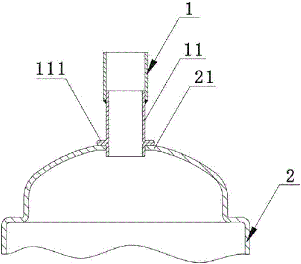
[0027] One end 11 of the pipe fitting is made of steel material, one end 11 of the pipe fitting extends from the neck 21 of the casing into the casing 2, and the neck 21 of the casing is made of steel material; the welding method using electric energy as a heat source One end 11 of the pipe fitting and the neck 21 of the casing are welded by welding.
[0028] The welding method of the pipe fitting and the casing provided in this embodiment is applied to the welding of the air intake pipe and the casing of the compressor accumulator, such as Figure 1a shown. Among them, the shell 2 is a liquid accumulator shell made of steel material (only the end cover part of the shell is shown in the figure); the pipe fitting 1 is the air intake pipe of the liquid accumulator, and the pipe fitting 1 is a composite pipe with a One end 11 made of stainless steel material and the other end 12 ...
Embodiment 2
[0036] The welding method of the pipe fitting and the shell provided by this embodiment includes:
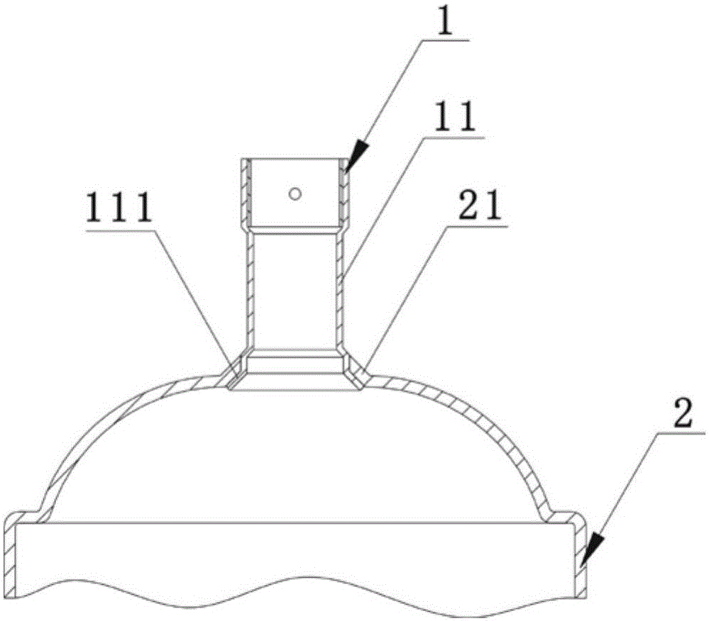
[0037] One end 11 of the pipe fitting is made of steel material, one end 11 of the pipe fitting extends from the neck 21 of the casing into the casing 2, and the neck 21 of the casing is made of steel material; the welding method using electric energy as a heat source One end 11 of the pipe fitting and the neck 21 of the casing are welded by welding.
[0038]In this embodiment, the welding method using electric energy as the heat source is arc welding. Preferably, the arc welding is gas tungsten arc welding. However, the present invention is not limited to this. In other embodiments, the arc welding can be any one of gas metal arc welding, plasma welding, or quasi-ion welding.
[0039] In this embodiment, the casing 2 is a compressor accumulator casing made of steel material, and the pipe fitting 1 is an air intake pipe of the compressor accumulator, such as Figure 2a shown...
Embodiment 3
[0045] The welding method of the pipe fitting and the shell provided by this embodiment includes:
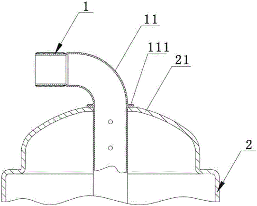
[0046] One end 11 of the pipe fitting is made of steel material, one end 11 of the pipe fitting extends from the neck 21 of the casing into the casing 2, and the neck 21 of the casing is made of steel material; the welding method using electric energy as a heat source One end 11 of the pipe fitting and the neck 21 of the casing are welded by welding.
[0047] In this embodiment, the welding method using electric energy as the heat source is brazing in which the heat source is electric energy, that is, non-flame brazing. Preferably, the brazing in which the heat source is electrical energy is argon arc brazing, such as Figure 3a shown, wherein the gas shield is not shown. However, the present invention is not limited to this. In other embodiments, the brazing in which the heat source is electrical energy may be molten electrode inert gas arc brazing (MIG brazing), molten elec...
PUM
 Abstract
Description
Claims
Application Information