An organic waste treatment furnace

An organic waste, treatment furnace technology, applied in incinerators, combustion methods, lighting and heating equipment, etc., can solve the problems of uncompact structure, large space occupation, low thermal efficiency, etc., achieve compact structure, reduce occupation space, The effect of uniform heating

Active Publication Date: 2017-11-14
江苏碧诺环保科技有限公司
View PDF8 Cites 2 Cited by
  • Summary
  • Abstract
  • Description
  • Claims
  • Application Information

AI Technical Summary

Problems solved by technology

[0005] Therefore, the technical problem to be solved by the present invention lies in the problem that the organic waste treatment equipment in the prior art occupies a large space and is not compact in structure, so an organic waste treatment furnace with a small space occupation and a compact structure is proposed
[0006] The technical problem to be solved by the present invention lies in the problem of uneven carbonization and low thermal efficiency in organic waste treatment equipment in the prior art, so an organic waste treatment system with uniform carbonization and high thermal efficiency is proposed

Method used


Image

  • An organic waste treatment furnace
  • An organic waste treatment furnace
  • An organic waste treatment furnace

Examples


Embodiment 1

[0034] This embodiment provides an organic waste treatment furnace, including:

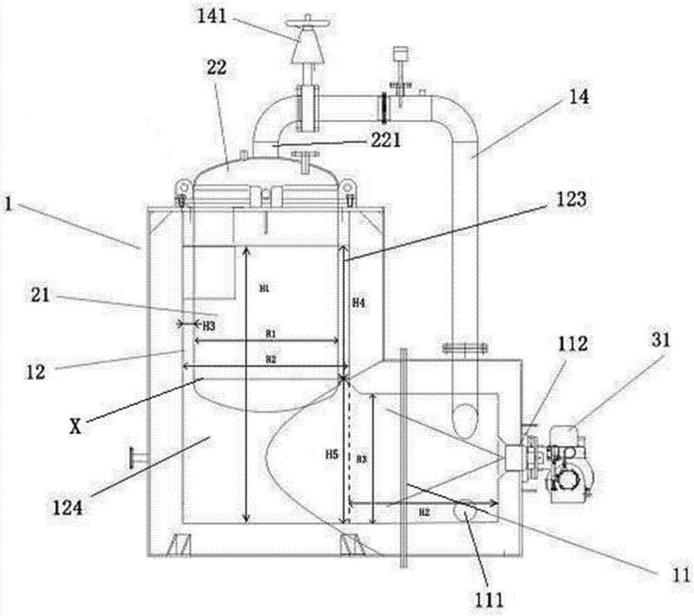
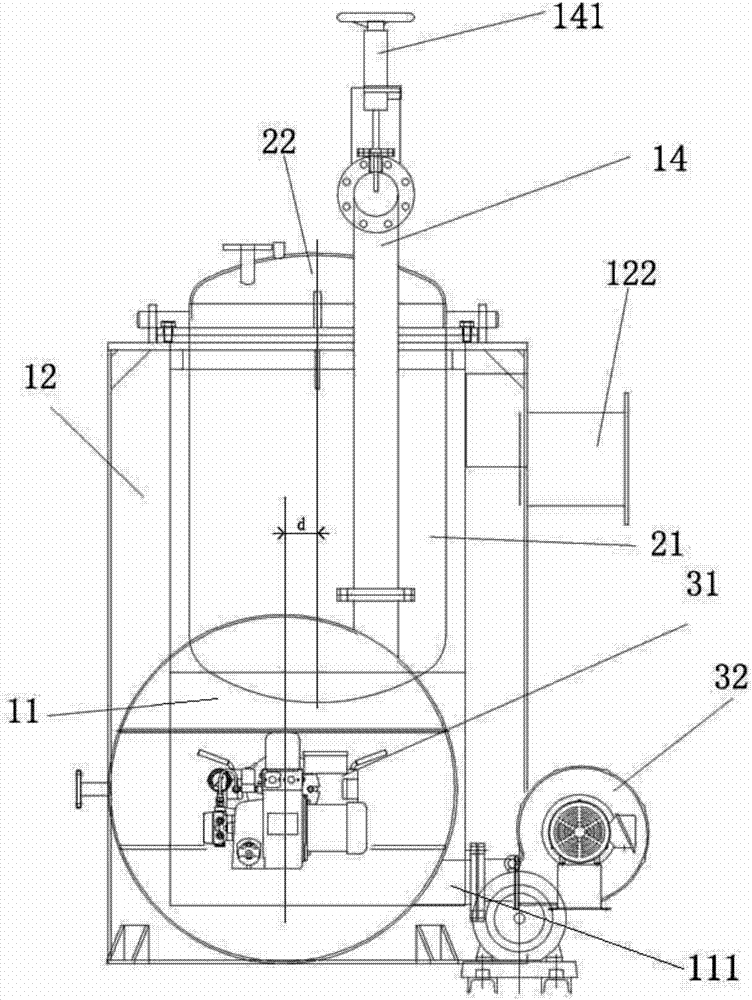
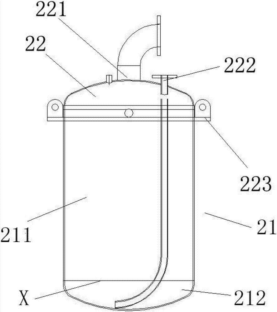
[0035] The combustion chamber has a vent 111 and a fuel inlet 112, the combustion-supporting gas is introduced through the vent 111, the fuel is introduced through the fuel inlet 112, and the combustion of the fuel provides the heating chamber with high-temperature gas; the heating chamber communicates with the combustion chamber, It is used to receive the high-temperature gas from the combustion chamber, and heat the accommodating chamber through the high-temperature gas; the accommodating chamber is used to carry organic waste and carbonize the organic waste, and has a carbonization gas discharge port 221; the cooling device 4 is arranged in the The exhaust port 122 on the heating chamber communicates for cooling the waste gas from the exhaust port 122; the dust removal device 5 communicates with the cooling device 4 for removing the dust in the gas discharged from the cooling device 4; the exhau...

Embodiment 2

[0053] This implementation provides an organic waste treatment furnace. The difference from Example 1 is that the ratio of the height H4 of the side heating channel to the width H3 of the side heating channel is 11:1; The ratio of the inner diameter R2 of the straight extending chamber 12 to the width H3 of the side heating channel is 14:1; the ratio of the height H5 of the bottom heating channel to the inner diameter R3 of the horizontally extending chamber 11 is 1.1:1; The ratio of the inner diameter R3 of the extending chamber 11 to the inner diameter R2 of the vertically extending chamber 12 is 0.65:1; the ratio of the inner diameter R2 of the vertically extending chamber 12 to the outer diameter R1 of the tank body 21 is 1.1:1. The ratio of the eccentric distance d to the inner diameter R2 of the vertically extending chamber 12 is 0.12:1. The ratio of the height H1 of the vertically extending chamber 12 to the length H2 of the horizontally extending chamber 11 is 1.6:1. ...

Embodiment 3

[0055] This implementation provides an organic waste treatment furnace. The difference from Example 1 is that the ratio of the height H4 of the side heating channel to the width H3 of the side heating channel is 12:1; The ratio of the inner diameter R2 of the straight extending chamber 12 to the width H3 of the side heating channel is 15:1; the ratio of the height H5 of the bottom heating channel to the inner diameter R3 of the horizontally extending chamber 11 is 1.2:1; The ratio of the inner diameter R3 of the extending chamber 11 to the inner diameter R2 of the vertically extending chamber 12 is 0.7:1; the ratio of the outer diameter R1 of the tank body 21 to the inner diameter R2 of the vertically extending chamber 12 is 1.2:1. The ratio of the eccentric distance d to the inner diameter R2 of the vertically extending chamber 12 is 0.15:1. The ratio of the height H1 of the vertically extending chamber 12 to the length H2 of the horizontally extending chamber 11 is 1.7:1. T...


PUM


Abstract

The invention relates to an organic waste processing furnace. The organic waste processing furnace is provided with an L-shaped outer furnace body with a horizontally-extending cavity and a vertically-extending cavity, a tank body is arranged on the vertically-extending cavity, and a burning chamber is directly connected with a heating chamber, so that the occupation space of the L-shaped outer furnace body is greatly reduced, and the structure is more compact. In addition, the outer lateral wall of the tank body is surrounded by a lateral heating channel, and the bottom of the tank body is wrapped and heated by a bottom heating channel; and after high-temperature gas coming from the horizontally-extending cavity enters the vertically-extending cavity, the bottom of the tank body is heated through the bottom heating channel, and meanwhile the lateral wall of the tank body is synchronously heated through a lateral heating channel surrounding the outer lateral wall of the tank body in the circumferential direction, so that all outer walls, located in the vertically-extending cavity, of the tank body can be evenly heated by the high-temperature gas, and meanwhile carbonization of the organic waste in the tank body is more uniform.

Description

technical field [0001] The invention relates to an organic waste treatment furnace, which belongs to the field of environmental protection equipment. Background technique [0002] In the prior art, the treatment of organic wastes such as municipal solid waste, harmful sick and dead animals and medical waste often adopts the method of incineration, and pyrolysis (combustion) treatment is carried out in an aerobic state. Ammonia nitrogen in organic waste is pyrolyzed (burned) in the state of oxygen to produce nitrogen oxides; sulfur is pyrolyzed (burned) in the state of oxygen to produce sulfur dioxide; chlorine is pyrolyzed (burned) in the state of oxygen to produce di Oxygen; carbon pyrolysis (combustion) in the presence of oxygen to produce carbon dioxide, etc. Therefore, when using incineration to treat organic waste, it is necessary to be equipped with a more complicated tail gas treatment system, otherwise the toxic and harmful substances such as dioxins, nitrogen oxide...

Claims


Application Information

Patent Timeline
Patent Type & Authority Patents(China)
IPC IPC(8): F23G1/00F23G7/00
CPCF23G1/00F23G7/00
Inventor 蒋子才蒋子厚
Owner 江苏碧诺环保科技有限公司
Why Eureka
Try Eureka